Du line
Æ
Fieldbus
Installationbus
Specifications are subject to change without notice (26.03.01)
1
Dupline
Æ
is a registered trademark. A product of the CARLO GAVAZZI Group
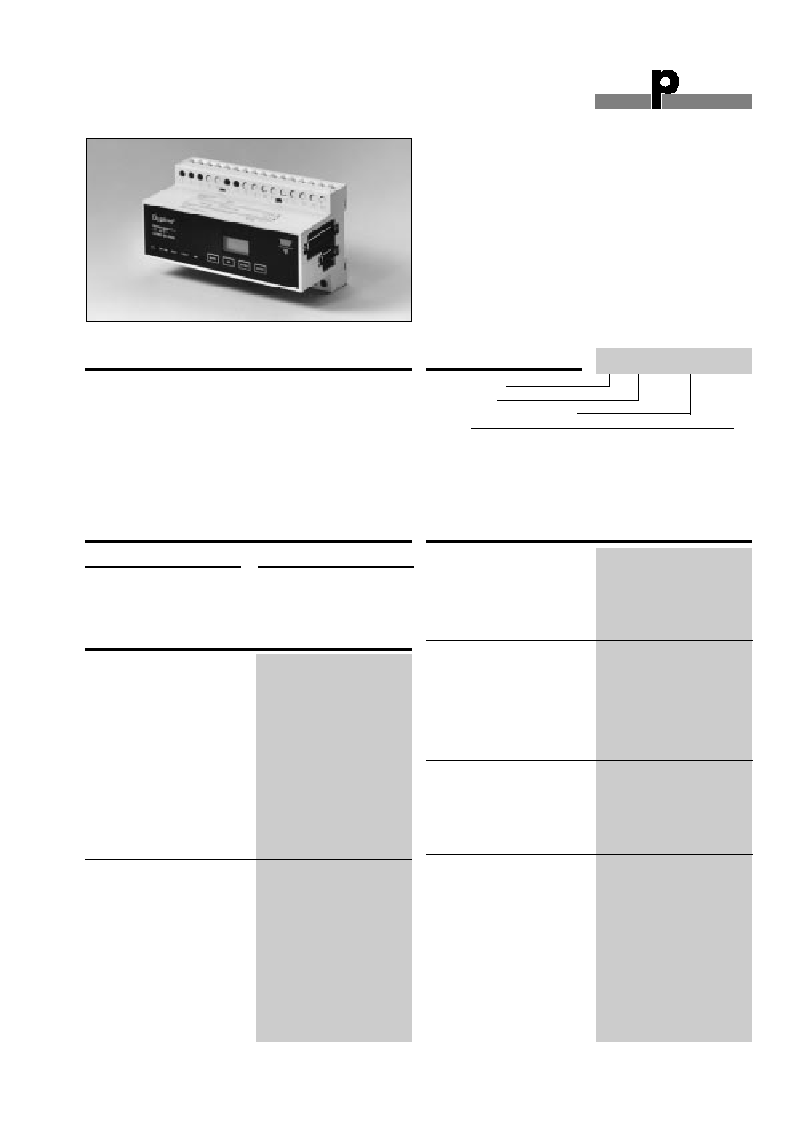
Product Description
Ordering Key
Type: Dupline
Æ
H8-housing
Master channel generator
Supply
Master Channel Generator
Type G 3890 0014
∑ Programmable channel generator
∑ Configuration based on Windows 95/98/NT software
∑ Light control functions
∑ Alarm monitoring
∑ AnaLink set-point control
∑ Rollerblind control
∑ Real-time, timer and logic functions
∑ Print-out of events with date and time tags
∑ Alarms and events can be sent as SMS to GSM-phones
(Only version <3.00)
∑ Controlling of functions via SMS from GSM-phones
(Only version <3.00)
∑ H8-housing
∑ For DIN-rail mounting (EN 50022)
∑ AC or DC power supply
∑ Modbus-RTU interface RS 232 (only version > 2.02)
∑ Option for connecting two Dupline
Æ
Master Channel
Generator Networks (only version > 2.02)
∑ Multiplex or normal mode
Programmable channel gen-
erator with built-in intelligent
functions for light control,
alarm monitoring, AnaLink
set-point control, rollerblind
control etc. Programming is
easily performed through
windows-based configuration
software. A specific function
with associated parameters
can be assigned to each
address and logic operations
can be used to link the func-
tions together. Surveillance
and control of functions can
be made via SMS from GSM-
phones by means of the
GSM8 modem.
Supply
Ordering no.
115/230 VAC
G 3890 0014 230
10 to 30 VDC
G 3890 0014 800
Type Selection
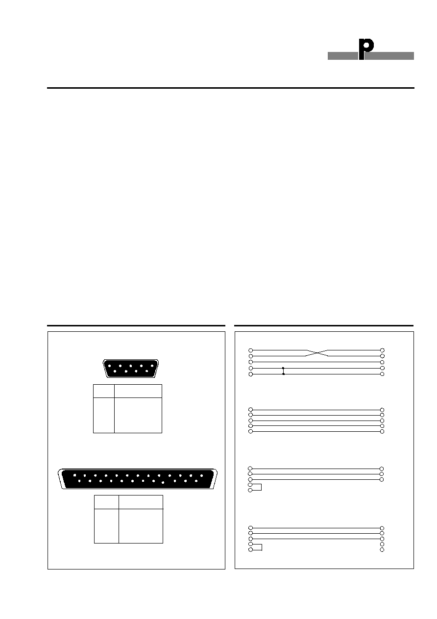
Serial Port
RS 232
9-pole female SUB-D
Pin assignment
TxD
Pin 2
RxD
Pin 3
GND
Pin 5
Dielectric voltage
Com.port - Dupline
Æ
2 kVAC (rms)
Parallel Port
Centronic
25-pole female SUB-D
Pin assigment
Strobe
Pin 1
Data D0-D7
Pins 2-9
Busy
Pin 11
Paper out
Pin 12
GND
Pins 18-25
Dielectric voltage
Com.port - Dupline
Æ
2 kVAC (rms)
Dupline
Æ
-Output
Dupline
Æ
carrier
Output voltage
8.2 V
Current
< 100 mA
Short-circuit protection
Yes
Sequence time
32 channels
38.6 ms
128 channels
132.3 ms
Watchdog-Output
1 NPN transistor
Function
Watchdog
Output voltage V
DD
35 VDC
Output current
100 mA
Output voltage drop
2 V
Off-state leakage current
100 µA
Short-circuit protection
None
Built-in protective diodes
None
Dielectric voltage
Output - Dupline
Æ
4 kVAC (rms)
Output - Input
4 kVAC (rms)
Inductive loads
External noise suppression
required
Input/Output Specifications
Supply Specifications
Power supply
AC-Types
Overvoltage cat. III (IEC 60664)
Rated operational voltage
through term. 21 & 24
jumper term. 22 & 23
230 VAC ± 15% (IEC 60038)
jumper term. 21 & 23
and term. 24 & 22
115 VAC ± 15% (IEC 60038)
Frequency
45 to 65 Hz
Rated operational power
Typ. 7 VA/3 W
Rated impulse withstand
voltage
115/230 V
4 kV
Dielectric voltage
Supply - Dupline
Æ
4 kVAC (rms)
Supply - Output
4 kVAC (rms)
Supply - Input
4 kVAC (rms)
Supply - Com. ports
4 kVAC (rms)
Power supply
DC-Types
Overvoltage cat. III (IEC 60664)
Rated operational voltage
through term. 21 & 22
10-30 VDC
Reverse polarity protection
Yes
Rated operational power
7 W
Inrush current
1 A
Rated impulse withstand volt. 800 V
Dielectric voltage
Supply - Dupline
Æ
500 V
Supply - Output
200 V
G 3890 0014 230
Du line
Æ
Fieldbus
Installationbus
2
Specifications are subject to change without notice (26.03.01)
Dupline
Æ
is a registered trademark. A product of the CARLO GAVAZZI Group
G 3890 0014
Input
Back-up supply
Function
Real-time clock
Isolated in groups of
1 x 1
Input voltage range
4.5 to 9 V
Reverse polarity protection
Yes
Rated operational current
10 to 100 µA
Input resistance
> 47 k
Cable length
< 0.5 m
Dielectric voltage
Input - Dupline
Æ
(230 V Version)
4 kVAC (rms)
Input - Dupline
Æ
(800 V Version) 500 V
Adjustment
Time, Date, Year, Day
4 tactile pushbuttons
(Mode, Up, Down, Enter)
RS 232 functions
LPT functions
Communication
LPT
Centronic
For serial printer / DOS-
commands
RS232
Normal mode
Download of configuration
Spec. mode
Modbus-RTU protocol
(Short-cut pin 7 and pin 8)
Txd
Pin 2
Rxd
Pin 3
Gnd
Pin 5
RTS
Pin 7
CTS
Pin 8
Input/Output Specifications (cont.)
Real-time clock
Accuracy
Better than ± 1 minute/month
Internal back-up time
Typ. 120 hours
Unit parameter back-up time
> 1 year
Power ON delay
< 2.5 s
Indication for
Supply ON
LED, green
ON Line
LED, yellow
Busy
LED, yellow
Fault
LED, red
Time, date etc.
4-digit LCD display
red background light
Environment
Degree of protection
IP 20
Pollution degree
3 (IEC 60664)
Operating temperature
0∞ to +50∞C (+32∞ to +122∞F)
Storage temperature
-20∞ to +85∞C (-4∞ to +185∞F)
Humidity (non-condensing)
20 to 80% RH
Mechanical resistance
Shock
15 G (11 ms)
Vibration
2 G (6 to 55 Hz)
Dimensions
Material
(see "Technical Information")
H8-housing
Weight
540 g
General Specifications
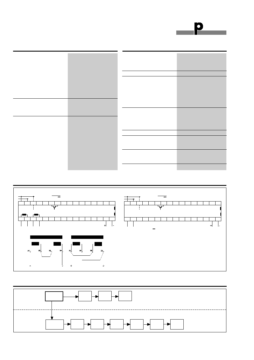
Wiring Diagrams
Key Operation Diagram
Set-Up
[SEt]
Set
Time
[HrS]
Time
Format
[FOr]
Set
Date
[dAtE]
Display
Time of day
Show
date
Show
year
Show day
of the
week
Date
Format
[FOr]
Set
Day
[dAY]
Set
Year
[YEAr]
Main Setting Mode
Power supply
230 VAC
Power supply
115 VAC
Centronic
RS 232
Backup
4.5-9 V
Watchdog NPN
Noise red.
G 3890 0014 800
Dupline
Æ
S
Supply 10-30 VDC 7 W
+
-
+
-
1
2
3
4
5
6
7
8
9
10
11
12
13
14
15
16
21
22
23
24
25
26
27
28
29
30
31
32
33
34
35
36
0.1 A
35 V
Centronic
RS 232
Backup
4.5-9 V
Watchdog NPN
Noise red.
G 3890 0014 230
Dupline
Æ
S
Supply
+
-
1
2
3
4
5
6
7
8
9
10
11
12
13
14
15
16
21
22
23
24
25
26
27
28
29
30
31
32
33
34
35
36
0.1 A
35 V
Du line
Æ
Fieldbus
Installationbus
Specifications are subject to change without notice (26.03.01)
3
Dupline
Æ
is a registered trademark. A product of the CARLO GAVAZZI Group
G 3890 0014
Mode of Operation
The G 3890 0014 master gener-
ator is a programmable channel
generator which is particularly
well suited for building automa-
tion applications like lighting
control, rollerblind control, tem-
perature control, and alarm-
monitoring. Through an easy-to-
use windows-based configura-
tion software, the unit can be
configured to perform real-time
control, logic and timer func-
tions, ISA, water, smoke and
Intruder alarm-monitoring and
Code/ Door lock armouring.
Print-outs of time-tagged user-
defined text in case of channel
output changes.
Keys
In the display mode, the four
front-keys are used to change
the display showing time, date,
day of the week, year or soft-
ware revision of the master gen-
erator (Press < enter >). The keys
are also used to set the time,
date, day of the week, year and
definition of operation and
parameters of the parallel ports.
Display
The back-lighted 4-digit LCD
display is used to show all the
relevant information that can be
changed by using the keys. If no
key is pressed for 2 minutes, the
display automatically shows the
actual time. In case of an Error
the display shows an Error code.
Back-up Terminals
In case of missing power the
internal calendar and clock are
supported by a super-capacitor.
Under normal ambient tempera-
ture this back-up will maintain
the correct date and time for
typically 5 days. If longer power
shutdowns can occur, an exter-
nal battery of 4.5 to 9 VDC may
be connected between terminal
35 (+) and terminal 36 (-).
Alarm Output Terminals
An open collector NPN-transistor
output with NC function signals
alarms and faults in the system.
Attention by the local personnel
is requested whenever this out-
put switches off. The display
and/or the LED¥s gives an indi-
cation of the cause of problem.
Master Generator Configura-
tion
The master generator is as fac-
tory default configured to oper-
ate as a standard channel-gen-
erator without intelligent func-
tions. To obtain full utilisation of
the advanced features, the gen-
erator has to be configured.
For configuration, the delivered
software SW G 3890 0014 has
to be installed on a Win
95/98/NT based PC.
This software handles all config-
uration of the G 3890 0014 mas-
ter generator. The software ver-
sion must be consistent with the
firmware version of the Master
Generator. Press <Enter> on top
of the Master Generator to see
the version in the display.
Configuration is done entirely on
the PC, and when completed,
the set-up is downloaded into
the generator via the serial port.
(COM1 or COM2).
Two Dupline
Æ
networks*
Two channel generators can be
connected via communication
cable. Thereby addresses, i.e.
master commands, can be
transferred from one network to
the other by means of the matrix
mapping in the configuration
software. Entering "1" in the
desired Dupline
Æ
address per-
forms selection of the channel
status from the other Dupline
Æ
network.
Modbus-RTU*
Modbus-RTU is implemented as
a function of a slave. The follow-
ing Modbus functions are sup-
ported: 01, 02, 03, 05, 06 and 16.
See: Modbus-RTU Memory
Mapping.
SMS**
Surveillance and control of
Dupline
Æ
channels can take
place by means of the SMS
option. The G38900014 module
can call up several GSM phones,
when an event or alarm appears,
and a GSM phone can change
the status of a Dupline
Æ
chan-
nel/function. The last option is
"Dial-in number" and password
protected.
* Rev. 2.02 or higher required
**Rev 3.xx or higher required
Pin Assignment
RS 232 Cables
2
3
5
7
8
2
3
5
7
8
2
3
5
7
8
2
3
5
7
8
9-pin male
to controller #1
9-pin male
to controller
9-pin female
to PC
9-pin male
to Controller #2
5
9
1
6
Pin
Signal
2
T x D
3
R x D
5
Signal Ground
7
RTS
8
CTS
13
25
1
14
Pin
Signal
1
Strobe
2-9
Do - D7
11
Busy
12
Paper out
18-25
GND
Two Dupline
Æ
Networks Cable
Configuration Cable
2
3
5
7
8
2
3
5
9-pin male
to controller
9-pin female
to PC
Modbus RTU Cable
2
3
5
7
8
Term 4
Term 5
Term 1
9-pin male
to controller
GSM8
GSM modem Cable
Function Code 06
Preset single Register
Data Word
Address
MSB...HB
LB...LSB
1000
B8...B1
A8...A1
1001
D8...D1
C8...C1
1007
P8...P1
O8...O1
Du line
Æ
Fieldbus
Installationbus
4
Specifications are subject to change without notice (26.03.01)
Dupline
Æ
is a registered trademark. A product of the CARLO GAVAZZI Group
Accessories
User manual
MAN G3890 0014 ENG
GSM modem
GSM8
For further information refer to "Accessories".
1 x Master Channel Generator
G 3890 0014 ..
1 x User manual
MAN G 3890 0014 ENG
1 x RS 232 cable
RS 232-9 M/9 F
1 x Configuration software
SW G 389XX14 version 3.00
Scope of Supply
Function Code 03
Read Multiple Registers
Data Word
Address
MSB...HB
LB...LSB
0000
B8...B1
A8...A1
0001
D8...D1
C8...C1
0007
P8...P1
O8...O1
0100
Analink A1
0101
Analink A2
017F
Analink P8
0200
#0
0..99
0..99
0..99
0..99
0202
#1
0..99
0..99
0..99
0..99
0204
#2
0..99
0..99
0..99
0..99
2FC
#126
0..99
0..99
0..99
0..99
2FE
#127
0..99
0..99
0..99
0..99
Modbus-RTU Memory Mapping
Function code 01
Read Output Table
Dupline
Æ
Channel
Address
500
A1
501
A2
57F
P8
Function code 02
Read Input Table
Dupline
Æ
Channel
Address
600
A1
601
A2
67F
P8
Function code 05
Set single Output Bit
Dupline
Æ
Channel
Address
1500
A1
1501
A2
157F
P8
Function Code 16
Preset Multiple Registers
Data Word
Address
MSB...HB
LB...LSB
1000
B8...B1
A8...A1
1001
D8...D1
C8...C1
1007
P8...P1
O8...O1