Du line
Æ
Fieldbus
Installationbus
Specifications are subject to change without notice (28.09.99)
1
Dupline
Æ
is a registered trademark. A product of the CARLO GAVAZZI Group
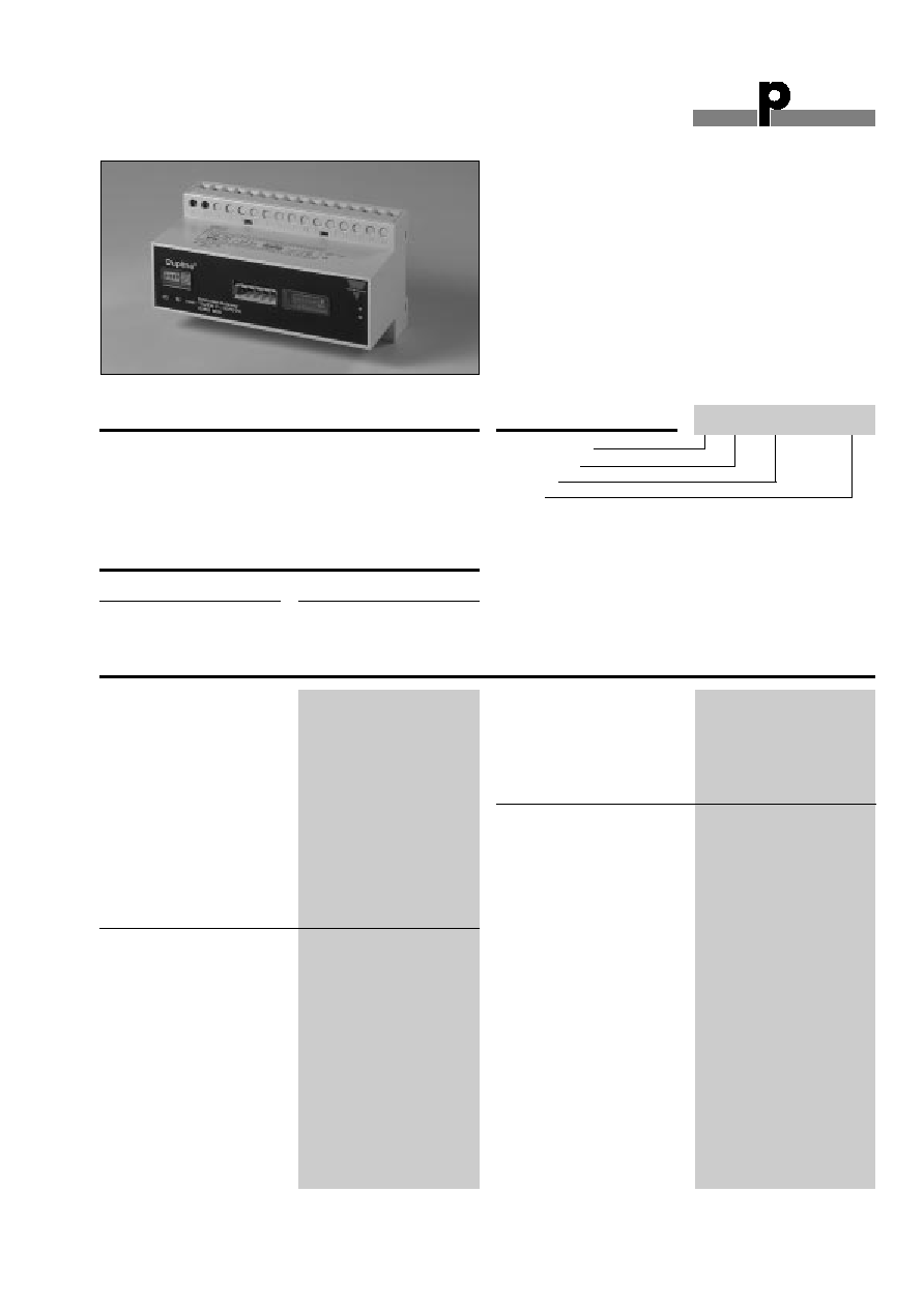
Product Description
Ordering Key
Type: Dupline
Æ
H8-Housing
Type no.
Supply
Dupline
Æ
DeviceNet Gateway
Type G 3891 0050
∑ Built-in Dupline
Æ
channel generator
∑ DeviceNet slave
∑ DeviceNet communication speed of up to 500 kBaud
∑ Read/control of 128 Dupline
Æ
inputs/outputs through
DeviceNet
∑ Split-I/O mode selectable (128 inputs and 128 outputs)
∑ Support of 3 1/2 digit BCD and AnaLink analog formats
∑ All Dupline
Æ
formats (except 8 bit binary multiplexed)
available on the DeviceNet network
∑ For mounting on DIN-rail (EN 50 022)
∑ LED indicators for supply, Dupline
Æ
carrier and fault
∑ AC power supply
Dupline
Æ
Channel Generator
with the function of a Device-
Net slave. This means that the
128 Dupline
Æ
I/O's can be
read/controlled by DeviceNet
masters (PLC's, PC interface
cards, etc. from various sup-
pliers). Several Dupline
Æ
gate-
ways can be connected to the
same DeviceNet network.
Supply
Ordering no.
115/230 VAC
G 3891 0050
Type Selection
DeviceNet
Pin assignment
V-
Pin 1
CAN-L
Pin 2
SHIELD
Pin 3
CAN-H
Pin 4
V+
Pin 5
Baudrate
Switch settings
Cable length (Thick cable)
100 m @ 500 kBaud
200 m @ 250 kBaud
1200 m @ 125 kBaud
Update time (128 digital I/O)
Typ. 200 µs at 560 kBaud
Typ. 1.6 ms at 125 kBaud
Dielectric voltage
DeviceNet Dupline
Æ
4 kVAC (rms)
EDS-file
Dupline
Æ
Output voltage
8.2 V
Output current
100 mA
Short-circuit protection
Yes
All channels ON detector
Yes
Output impedance
15
Sequence time
8 digital I/O
15.2 ms
128 digital I/O
132.3 ms
AnaLink value update time
8 signals
3.9 s
128 signals
33.8 s
Input/Output Specifications
G 3891 0050 230
Adjustments
1 x 16 pos. rotary switch
No. of Dupline
Æ
channels
8 .. 128 in steps of 8
DIP-switch 1
Dupline
Æ
mode (Normal/Split I/O)
DIP-switch 2
Dupline
Æ
data transfer mode
DIP-switch 3
Analog input
DIP-switch 4
Analog output
CE-marking
Yes

Du line
Æ
Fieldbus
Installationbus
2
Specifications are subject to change without notice (28.09.99)
Dupline
Æ
is a registered trademark. A product of the CARLO GAVAZZI Group
G 3891 0050
Power ON delay
< 2.5 s until start of
Dupline
Æ
carrier.
< 40 s until correct reading
of AnaLink values
Indication for
Supply ON
LED, green
Dupline
Æ
carrier
LED, yellow
Fault
LED, red
Environment
Degree of protection
IP 20
Pollution degree
3 (IEC 60664)
Operating temperature
0∞ to +50∞C (+32∞ to +122∞F)
Storage temperature
-20∞ to +85∞C (-4∞ to +185∞F)
Humidity (non-condensing)
20 to 80% RH
Mechanical resistance
Shock
15 G (11 ms)
Vibration
2 G (6 to 55 Hz)
Dimensions
H8-housing
Material
(see Technical information)
Weight
540 g
General Specifications
Mode of Operation
The Dupline
Æ
DeviceNet
Gateway is a Dupline
Æ
Chan-
nel generator with a function
of a DeviceNet slave. This
means that the 128 Dupline
Æ
I/O's can be read/controlled
by DeviceNet masters like
PLC's and PC interface-
cards from many different
suppliers. Several Dupline
Æ
Gateways can be connected
to the same network and
operate together with other
DeviceNet modules like ope-
ratorpanels, MMI's I/O mo-
dules etc.
Configuration switches
The unit is equipped with
the following configuration
switches. (See also switch
settings)
1x16 position rotary-switch
for selecting Number of
Dupline
Æ
Channels in the
range 8..128 (in steps of 8).
The selected letter indicates
the last channel group
available on Dupline
Æ
. If e.g.
H is selected, the 64 chan-
nels in groups A..H will be
available.
1x DIP-switch for selection of
Dupline
Æ
Operation Mode.
In "Normal" mode, Dupline
Æ
operates as a peer-to-peer
system where the channel
generator automatically es-
tablishes a connection be-
tween Dupline
Æ
inputs and
Dupline
Æ
outputs which are
coded to the same Dupline
Æ
address. If e.g. an input
coded for B5 is activated,
the output(s) coded for B5
will also be activated. Con-
sequently, a Dupline
Æ
output
can either be activated through
the output-data received on
DeviceNet or by an active
Dupline
Æ
input coded for the
same Dupline
Æ
address.
In "Split I/O" mode, the
Dupline
Æ
inputs and Dupline
Æ
outputs are treated indepen-
dently by the channel gene-
rator. If e.g. and input coded
for B5 is activated, the
Gateway will make the infor-
mation available on Device-
Net (like in normal mode), but
it will not automatically ac-
tivate the Dupline
Æ
output(s)
coded to B5. The Dupline
Æ
outputs are controlled exclu-
sively through the output data
received on DeviceNet.
1x DIP-switch for selection of
analog data.
In OFF position only Digital
In/Out data are transferred.
To enable analog data-I/O
handling this DIP-switch
must be ON.
1x DIP-switch for selection of
Analog input operation mode.
When OFF the analog input
data are read as AnaLink.
Each channel from C1 to P8
are read as 8 bit analog data.
When ON the analog input
data are considered as 3 1/2
digit multiplexed data. The
multiplex-control (Synchroni-
zation) are automatically set
Wiring Diagrams
Power supply
230 VAC
Power supply
115 VAC
17 VA
S
1
2
3
4
9
8
7
6
5
12
11
10
15
14
13
16
21
22
23
24
29
28
27
26
25
32
31
30
35
34
33
36
Network Status
Module Status
Baud Address
Dupline
Settings
No
Channels
V-
V+
CAN-L
CAN-H
SHIELD
1 2 3 4
ON
P
N
N P
115V
115V
SUPPLY
Supply Specifications
Power supply
Overvoltage cat. III (IEC 60664)
Rated operational voltage
through term. 21, 22, 23 & 24 See wiring diagram
230
230 VAC ± 15% (IEC 60038)
115
115 VAC ± 15% (IEC 60038)
Frequency
45 to 65 Hz
Rated operational power
11 VA
Rated impulse withstand
voltage
230
4 kV
115
2.5 kV
Dielectric voltage
Supply - Dupline
Æ
4 kVAC (rms)
Supply - RS 485
4 kVAC (rms)

Du line
Æ
Fieldbus
Installationbus
Specifications are subject to change without notice (28.09.99)
3
Dupline
Æ
is a registered trademark. A product of the CARLO GAVAZZI Group
G 3891 0050
to operate on channels
A1..A4 which then can not
be used for other purposes.
1xDIP-switch for selection of
Analog Output operation
mode.
When OFF the Analog output
are emitted as AnaLink.
When ON the Analog Out-
put-data are emitted as 3 1/2
digit Multiplexed data, and
channels A1..A4 will control
the multiplex addressing .
Dupline
Æ
Input Data
A part of the Gateway input-
processor reads all the 128
Dupline
Æ
-channels as Digital
inputs (16 bytes) and another
part reads the 112 channels
(C1 to P8) as Analog inputs
and performs the appropriate
scaling of input data. Each
Analog value are represented
as a 16 bit word with MBS as
sign and 15 bits of magnitu-
de. This results in a total of
224 bytes contaning all ana-
log input-data.
All data are mapped with
Digital input bytes starting at
relative address 00 followed
by the analog data. See
In/out data mapping.
Dupline
Æ
Output Data
Digital Output data are hand-
led in accordance with the
Dupline
Æ
Operation Mode:
Split I/O or Normal. Analog
data are handled and scaled
in accordance to Analog
Output operation mode.
When Analog Output is sele-
cted, care should be taken to
avoid a mix of Digital and
analog output data.
The AnaLink Outputs a seri-
es of pulsating 1's and 0's
and for the value of zero, a
basic 8 pulse-train will be
outputed, for enabling the
receivers to detect validity.
When outputting Multiplexed
Analog, two bits are output
for format-check.
To disable analog outputs,
write a value of -32767
(0xFFFF) in all locations whe-
re only digital data should be.
If eg. channels O1 .. P8 are
desired as purly digital data,
all analog data bytes map-
ped from relative address
0xD0 to 0XEF should be
written the value 0xFF.
Mode of Operation (cont.)
Relative Addressing of Input/Output Data
adr:
00:
A-P Digital
16
bytes
10:
C-D Analog
32
bytes
30:
E-F Analog
32
bytes
50:
G-H Analog
32
bytes
70:
I-J Analog
32
bytes
90:
K-L Analog
32
bytes
B0: M-N Analog
32
bytes
D0: O-P Analog
32
bytes
Adr:
MSB
LSB
00:
A1.
A8
01:
B1.
02:
Adr:
10-11:
C1: AnaLink or C-D mux 0
12-13:
C2: AnaLink or C-D mux 1
2E-2F:
D8: AnaLink or C-D mux 15
Analog data format:
Adr: 10
11
Bits: 7.6.5.4.3.2.1.0
7.6.5.4.3.2.1.0
15 bits magnitude
sign
0: positive
1: negative = Disabled
Digital data
Analog data
Input/Output area

Du line
Æ
Fieldbus
Installationbus
4
Specifications are subject to change without notice (28.09.99)
Dupline
Æ
is a registered trademark. A product of the CARLO GAVAZZI Group
Switch Settings
ON
1 2 3 4
Number of Dupline Channels
A: Group A
8 channels
B: Groups A..B
16 channels
P: Groups A..P
128 channels
1: Dupline Operation Mode
OFF:
Normal (Peer-to-Peer)
ON:
Split I/O mode
2: Dupline Data Transfer mode
OFF:
Digital
ON:
Analog
3: Analog Input protocol
OFF:
AnaLink
ON:
Multiplex
4: Analog Output protocol
OFF :
AnaLink
On:
Multiplex
Pin Assignment - DeviceNet Connector
1
2
4
3
5
Plugable connector
Screw terminals
Description
1
1
V-
2
2
CAN-L
3
3
SHIELD
4
4
CAN-H
5
5
V+
G 3891 0050
Baud Address
0
1
1
8
ON
Network Status
Module Status
BUS connector
LED's
Description
Module-Status, steady off
No power
Module-Status, steady red
Unrecoverable fault
Module-Status, steady green
Device Operational
Module-Status, flashing red
Minor fault
Network-Status, steady off
Not Powered/Not on line
Network-Status, steady green
Link OK on line, Connected
Network-Status, steady red
Critical Link failure
Network-Status, flashing green
On line not connected
Network-Status, flashing red
Connection Time Out
Module errors are indicated with the Module status
LED and Network status LED
Baudrate bit/s
Set DIP 1-2
125k
00
250k
01
500k
10
Reserved
11
Address
Set DIP 3-8
0
000000
1
000001
2
000010
61
111101
62
111110
63
111111