Du line
Æ
Fieldbus
Installationbus
Specifications are subject to change without notice (21.08.2006)
1
Dupline
Æ
is a registered trademark. A product of the CARLO GAVAZZI Group
Product De scrip tion
Ordering Key
Type: Dupline
Æ
H8-Housing
Type no.
Supply
Dupline
Æ
Field- and Installationbus
Dupline
Æ
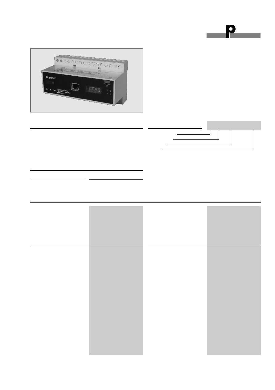
Ethernet Modbus/TCP Gateway
Type G 3891 0052
∑ Built-in Dupline
Æ
channel generator
∑ Modbus/TCP Slave
∑ 10 and 100 Mbit operation, full or half duplex
∑ Twisted pair cables
∑ Read/control 128 Dupline
Æ
inputs/outputs
∑ Split-I/O mode selectable (128 inputs and 128 outputs)
∑ Support of 3 1/2 digit BCD and AnaLink analog formats
∑ For mounting on DIN-rail (EN 50 022)
∑ LED indicators for supply, Dupline
Æ
carrier and fault
∑ LED indicators for Ethernet link, module status and
activity
∑ AC power supply
Dupline
Æ
Channel Generator
with the function of an Ether-
net Modbus/TCP slave. This
means that digital as well as
analog Dupline
Æ
I/O's can be
read/controlled from Mod-
bus/TCP masters (PC's, PLC's
etc.). The unit supports both
Analink and Multiplexed ana-
log signals. Several Dupline
Æ
gateways can be connected
to the same Ethernet network.
Supply
Ordering no.
115/230 VAC
G 3891 0052 230
Type Selection
Ethernet
Protocol
Modbus/TCP
Connector
RJ45 (standard)
Communication Speed
10 or 100 Mbit operation
IP address setting
via DIP-switches or PC (arp
command)
Dielectric voltage
Ethernet ≠ Dupline
Æ
4 kVAC (rms)
Dupline
Æ
Output voltage
8.2 V
Output current
100 mA
Short-circuit protection
Yes
All channels ON detector
Yes
Output impedance
15
Sequence time
132.3 ms (@ 128 channels)
Input/Output Spec i fi ca tions
G 3891 0052 230
Adjustments
1 x 16 pos. rotary switch
No. of Dupline
Æ
channels
8 .. 128 in steps of 8
DIP-switch 1
Dupline
Æ
mode (Normal/Split I/O)
DIP-switch 2
Dupline
Æ
analog
DIP-switch 3
Analog input protocol
DIP-switch 4
Analog output protocol
DIP-switch 5-12
IP address
CE-marking
Yes

Du line
Æ
Fieldbus
Installationbus
2
Specifications are subject to change without notice (21.08.2006)
Dupline
Æ
is a registered trademark. A product of the CARLO GAVAZZI Group
G 3891 0052
Power ON delay
< 2.5 s until start of
Dupline
Æ
carrier.
< 40 s until correct reading
of AnaLink values
Indication for
Supply ON
LED, green
Dupline
Æ
carrier
LED, yellow
Fault
LED, red
Ethernet Link
LED, green
Ethernet Module Status
LED, green/red
Ethernet Activity
LED, green
Environment
Degree of protection
IP 20
Pollution degree
3 (IEC 60664)
Operating temperature
0∞ to +50∞C (+32∞ to +122∞F)
Storage temperature
-20∞ to +85∞C (-4∞ to +185∞F)
Humidity (non-condensing)
20 to 80% RH
Mechanical resistance
Shock
15 G (11 ms)
Vibration
2 G (6 to 55 Hz)
Dimensions
H8-housing
Material
(see Technical information)
Weight
540 g
General Spec i fi ca tions
Mode of Operation
The Dupline
Æ
Ethernet Gate-
way is a Dupline
Æ
Channel Gen-
erator with the function of a
Modbus/TCP slave. This
means that the 128 Dupline
Æ
I/O's can be read/controlled by
Modbus/TCP masters like
PLC's and PC interface cards
from many different suppliers.
Several Dupline
Æ
Gateways can
be connected to the same net-
work and operate together with
other Ethernet modules like
operator panels, MMI's I/O
modules etc.
Dupline Configuration
switches
The unit is equipped with the
following Dupline configuration
switches. (See also switch set-
tings)
1x16 position rotary-switch for
selecting Number of Dupline
Æ
Channels in the range 8..128 (in
steps of 8). The selected letter
indicates the last channel group
available on Dupline
Æ
. If e.g. H
is selected, the 64 channels in
groups A..H will be available.
DIP-switch (1) for selection of
Dupline
Æ
Operation Mode. In
"Normal" mode, Dupline
Æ
oper-
ates as a peer-to-peer system
where the channel generator
automatically establishes a
connection between Dupline
Æ
inputs and Dupline
Æ
outputs
which are coded to the same
Dupline
Æ
address. If e.g. an
input coded for B5 is activated,
the output(s) coded for B5 will
also be activated. Consequent-
ly a Dupline
Æ
output can either
be activated through the out-
put-data received on Ethernet
or by an active Dupline
Æ
input
coded for the same Dupline
Æ
address. In "Split I/O" mode,
the Dupline
Æ
inputs and
Dupline
Æ
outputs are created
independently by the channel
generator. If e.g. and input cod-
ed for B5 is activated, the
Gateway will make the informa-
tion available on Ethernet (like
in normal mode), but it will not
automatically activate the
Dupline
Æ
output(s) coded to B5.
The Dupline
Æ
outputs are con-
trolled exclusively through the
output data received on Ether-
net.
Note: Analink output as well as
BCD multiplex data only work
in split I/O mode.
DIP-switch (2) for selection of
analog data. In OFF position
only Digital In/Out data are
transferred. To enable analog
data-I/O handling this DIP-
switch must be ON.
DIP-switch (3) for selection of
Analog input operation mode.
When OFF the analog input
data are read as AnaLink. Each
channel from C1 to P8 is read
as 8 bit analog data. When ON
the analog input data are con-
sidered as 3 _ digit BCD multi-
plexed data. The multiplex-con-
trol (Synchronization) are auto-
matically set to operate on
channels A1..A4, which then
cannot be used for other pur-
poses.
Wiring Diagrams
Power supply
230 VAC
Power supply
115 VAC
Supply Spec i fi ca tions
Power supply
Overvoltage cat. III (IEC 60664)
Rated operational voltage
through term. 21, 22, 23 & 24 See wiring diagram
230
230 VAC ± 15% (IEC 60038)
115
115 VAC ± 15% (IEC 60038)
Frequency
45 to 65 Hz
Rated operational power
11 VA
Rated impulse withstand
voltage
230
4 kV
115
2.5 kV
Dielectric voltage
Supply - Dupline
Æ
4 kVAC (rms)
Supply - RS 485
4 kVAC (rms)
21
1
9
2
10
1
2
3
4
3
11
4
12
5
13
6
14
7
15
8
16
29
22
30
23
31
24
32
25
33
26
34
27
35
28
36
DUPLINE
SUPPLY
115V
P
N
N
P
115V
DUPLINE
SETTINGS
1
2 3 4
ON
NO.
CHANNELS
ETHERNET CONNECTOR
IP ADDRESS
LEDS STATUS
+
D
D

Du line
Æ
Fieldbus
Installationbus
Specifications are subject to change without notice (21.08.2006)
3
Dupline
Æ
is a registered trademark. A product of the CARLO GAVAZZI Group
G 3891 0052
DIP-switch (4) for selection of
Analog Output operation mode.
When OFF the Analog outputs
are emitted as AnaLink. When
ON the Analog Output-data are
emitted as 3 _ digit Multiplexed
data, and channels A1..A4 will
control the multiplex address-
ing.
Note: Change of Dip-switch
settings During operation, may
cause reset of the Gateway.
Dupline
Æ
Input Data
A part of the Gateway input
processor reads all the 128
Dupline
Æ
-channels as Digital
inputs (16 bytes) and another
part reads the 112 channels (C1
to P8) as Analog inputs. Each
Analog value is represented as
a 16 bit word with MBS as sign
and 15 bits of magnitude. This
results in a total of 224 bytes
containing all analog input-
data. Since the sign of a valid
Dupline analog value is always
positive, the range is 0..32767,
where 32767 corresponds to
the max analog input. It is up to
the user to read the data in the
correct area (digital or analog)
according to the type of mod-
ule (digital or analog) he has
installed on a Dupline address.
All data are mapped with Digital
input bytes starting at relative
address 00 followed by the
analog data. See In/out data
mapping.
Dupline
Æ
Output Data
A memory area of 16 bytes is
available for control of the out-
puts of the 128 Dupline chan-
nels. If Normal mode is select-
ed, the outputs can also be
controlled from Dupline trans-
mitters (OR-function). A memo-
ry area of 224 bytes is available
for control of the 112 Analog
output values. The data must
be entered in the range
0..32767. The Gateway will
convert them to the right
Dupline format in accordance
with the selected Analog Out-
put operation mode. However
,Analink output works only in
split I/O mode. When Analog
transmission is selected it is
important to write the value
FFFF Hex (-32767 decimal) to
all those of the 112 output
addresses where no analog
output is desired. Otherwise the
digital transmission will be dis-
turbed. Also, in case 3 _ digit
BCD is selected, it should be
noted that sending out analog
values on one or more multiplex
addresses on a double-group
(e.g. C-D) will disable the use of
this entire double-group for dig-
ital transmission. However,
BCD multiplex data also works
only in split I/O mode.
IP address information
IP address
The IP address is used to iden-
tify each node on the TCP/IP
network. Therefore, each node
on the network must have a
unique IP address. IP address-
es are written as four decimal
integers (0-255) separated by
periods, where each integer
represents the binary value of
one byte in the IP address. This
is called dotted-decimal nota-
tion.
Example:
Address 10000000 00001010
00000010 00011110 is written
as 128.10.2.30
Subnet Mask
The IP address is divided into
three parts - net ID, subnet ID
and host ID. To separate the
net ID and the subnet ID from
the host ID, a subnet mask is
used. The subnet mask is a 32-
bit binary pattern, where a set
bit allocates a bit for
network/subnet ID, and a
cleared bit allocates a bit for
the host ID. Like the IP address,
the subnet mask is commonly
written in dotted-decimal nota-
tion.
Example:
To make the IP address
128.10.2.30 belong to subnet
128.10.2, the subnet mask shall
be set to 255.255.255.0.
Subnet Mask: 11111111
11111111 1111111 00000000
(255.255.255.0)
Net ID /Subnet ID/Host ID
Important Note: To be able to
establish communication
between two devices both
devices must belong to the
same subnet. If not, the com-
munication must be done
through a gateway. It is there-
fore recommended
to configure the module to the
same subnet as your PC (If e.g.
the PC has IP address
192.168.2.21, then the IP
address of the Dupline Ethernet
Gateway must have an IP
address 192.168.2.n , where n
is a number in the range
1..255).
IP address selection
The module offers two ways to
configure the IP-address:
∑ By using the DIP switches
in the front
∑ By using the arp-command
from a PC
Using the Configuration
Switch for selection of IP
address
The configuration switch pro-
vides an easy way to configure
the module for intranet use. The
switch represents the binary
value of the last byte in the IP
address. If the switch is set to a
value between 1-255 the mod-
ule will use the settings
described below. (If the switch-
es are all in the OFF-position,
corresponding to the value 0,
then the Gateway is set up to
be configured using the arp-
command from a PC.)
IP address: 192.168.0.n Subnet
mask: 255.255.255.0 Gateway
address: 0.0.0.0 (No gateway
set)
The last byte (n) represents the
binary value of the switches.
Subnet mask and Gateway
address settings are fixed to
the above values when using
the configuration switches.
Example:
The switches are set to
00010100 (20 decimal)
The IP address of the module
will be set to 192.168.0.20
Note: These settings can only
be used on an intranet. This is
because the IP address that is
being set belongs to the private
address set.
Using the Address Resolution
Protocol (ARP) for selection
of IP address
The IP address can be config-
ured (or changed during run-
time) using the ARP command
from a PC. Below is an exam-
ple on how to change the IP
address from a MS DOSTM win-
dow (which is normally avail-
able under "accessories" as
"Command prompt" in the win-
dows programs menu).
arp -s <IP address> <MAC
address>
ping <IP address>arp -d
<IP address>
Example:
To set the IP address to
192.168.2.21 on a Dupline Eth-
ernet Gateway with MAC
address 00-30-11-02-10-DA
the following commands should
be issued in the "command
prompt" window:
arp ≠s 192.168.2.21 00-30-11-
02-10-DA
ping 192.168.2.21
arp ≠d 192.168.2.21
The arp -s command will store
the IP and MAC addresses in
the PC's ARP table. When the
ping command
is executed, the PC sends this
information to the module using
the MAC address. The module
detects that it was addressed
with the correct MAC address
and adopts the IP address sent
by the PC. (The arp -d com-
mand is optional, but it
removes the static route from
the PC ARP table).
This method can be used to
reconfigure modules that
already has been configured, or
even to reconfigure modules
outside the host's subnet.
Important note:
The MAC
address is printed on a label on
the bottom side of the module.
Important note: As the Arp
command automatically config-
ures the subnet mask to
255.255.255.0, the first three
bytes of the IP address must be
the same as for the PC execut-
ing the command.
Example:
PC ≠ 192.168.2.67
Module- 192.168.2.n (Where n
is a value between 1 and 254)
Mode of Operation (cont.)
Modbus addr
Hex.
Dec.
0000
0000
A-P Digital
8
words
0008
0008
C-D Analog
16
words
0018
0024
E-F Analog
16
words
0028
0040
G-H Analog
16
words
0038
0056
I-J Analog
16
words
0048
0072
K-L Analog
16
words
0058 0088
M-N
Analog
16
words
0068 0104
O-P
Analog
16
words
Du line
Æ
Fieldbus
Installationbus
4
Specifications are subject to change without notice (21.08.2006)
Dupline
Æ
is a registered trademark. A product of the CARLO GAVAZZI Group
G 3891 0052
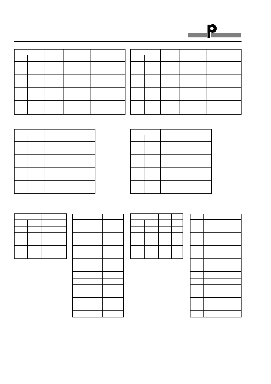
Modbus Memory Map
Input (Hexadecimal notation)
Modbus addr
Hex.
Dec.
0400
1024
A-P Digital
8
words
0408
1032
C-D Analog
16
words
0418
1048
E-F Analog
16
words
0428
1064
G-H Analog
16
words
0438
1080
I-J Analog
16
words
0448
1096
K-L Analog
16
words
0458 1112
M-N
Analog
16
words
0468 1128
O-P
Analog
16
words
Outputs (Hexadecimal notation)
Modbus addr
Hex.
Dec.
MSB
LSB
0000
0000
A1 B8
0001
0001
C1 D8
0006
0006
M1 N8
0007
0007
O1 P8
Digital input data
- bit memory map
Modbus addr
Hex.
Dec.
MSB
LSB
0400
1024
A1 B8
0401
1025
C1 D8
0406
1030
M1 N8
0407
1031
O1 P8
Digital output data
- bit memory map
Modbus addr
Hex.
Dec.
0008
0008
Analink C1 or C-D mux 0
0009
0009
Analink C2 or C-D mux 1
0017
0023
Analink D8 or C-D mux F
0018
0024
Analink E1 or E-D mux 0
0076
0118
Analink P7 or O-P mux E
0077
0119
Analink P8 or O-P mux F
Analog input data - memory map
Modbus addr
Hex.
Dec.
0408
1032
Analink C1 or C-D mux 0
0409
1033
Analink C2 or C-D mux 1
0417
1047
Analink D8 or C-D mux F
0418
1048
Analink E1 or E-D mux 0
0476
1142
Analink P7 or O-P mux E
0477
1143
Analink P8 or O-P mux F
Analog output data - memory map
ANALOG DATA FORMAT:
All analog values are scaled linearly to 15 bit binary format (Min analog value: 0 , Max analog value 32767)
Hex.
Dec.
Channel
0000
0
A1
0001
1
A2
0002
2
A3
0003
3
A4
0007
7
A8
0008 8
B1
000E
14
B7
000F
15
B8
0010
16
C1
0011
17
C2
007E
126
P7
007F
127
P8
Hex.
Dec.
Channel
4000
16384
A1
4001
16385
A2
4002
16386
A3
4003
16387
A4
4007
16391
A8
4008 16392
B1
400E
16398
B7
400F
16399
B8
4010
16400
C1
4011
16401
C2
407E
16510
P7
407F
16511
P8
Digital input data
- single bit references
Digital output data
- single bit references
Du line
Æ
Fieldbus
Installationbus
Specifications are subject to change without notice (21.08.2006)
5
Dupline
Æ
is a registered trademark. A product of the CARLO GAVAZZI Group
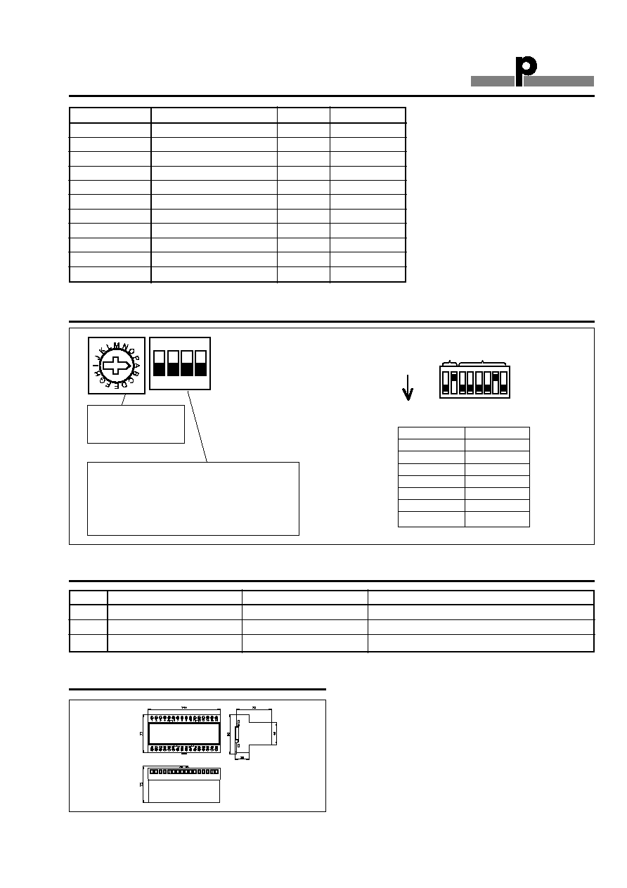
Switch Settings
ON
1 2 3 4
Number of Dupline Channels
A: Group A
8 channels
B: Groups A..B
16 channels
P: Groups A..P
128 channels
1: Dupline Operation Mode
OFF:
Normal (Peer-to-Peer)
ON:
Split I/O mode
2: Dupline Data Transfer mode
OFF:
Digital only
ON:
Digital + Analog
3: Analog Input protocol
OFF:
AnaLink
ON:
Multiplex
4: Analog Output protocol
OFF :
AnaLink
On:
Multiplex
IP Address
0
1
8
ON
IP Address
Set DIP 8
arp
00000000
192.168.0.1
00000001
192.168.0.2
00000010
192.168.0.253
11111101
192.168.0.254
11111110
192.168.0.255
11111111
Ethernet LED Indicators (right hand side of the module)
ON
OF
Blinking
LED 1
The module has a link
The module has no link
LED 2
IP address set via arp cmd
IP address set via switches
LED 4
Blinks when a packet is received or transmitted
Function Code
Function Name
Class
Affects Area
1
Read coils
1
IN/OUT
2
Read input discretes
1
IN/OUT
3
Read multiple registers
0
IN/OUT
4
Read input registers
1
IN/OUT
5
Write coil
1
OUT
6
Write single register
1
OUT
7
Read exception status
2
-
15
Force multiple coils
2
OUT
16
Force multiple registers
0
OUT
22
Mask write register
2
OUT
23
Read/Write registers
2
IN/OUT
G 3891 0052
Supported Modbus Function Codes
Dimensions (mm)
H8-housing