
Type: Dupline
Æ
"H4"- Housing
Dimmer
4 Channels
1 Output
MOSFET 600W Analog
Power Supply
Du line
Æ
Fieldbus
Installationbus
Specifications are subject to change without notice (20.12.05)
1
Dupline
Æ
is a registered trademark. A product of the CARLO GAVAZZI Group
Ordering Key
Product Description
The G4248 4134 lighting
scene dimmer is a compo-
nent of the Dupline Installation
System. It permits different
types of lamps with wattages
up to 600 W to be operated
and dimmed and enables up
to 6 lighting arrangements to
be stored which can then be
retrieved at any time. In addi-
tion, it transmits the status of
the dimming output and cur-
rent alarms.
The dimmer setting which
was selected last is stored as
a "memory setting" in the
internal memory and is rese-
lected next time the lighting is
switched on via channel 2 or
by the control button on the
front panel. A power failure
will erase the memory setting.
The brightness of the lighting
scenes is preset at the factory
in steps; these settings can-
not be altered. By the aid of
push-button combinations
(preferably via the "Master
Function" option provided in
the configuration software) or
by means of the test unit, the
lighting scenes can be
unlocked, modified and also
retrieved.
In addition to the load output,
the dimmer is equipped with
a control output to which up
to ten load modules can be
connected in order to in-
crease the dimming capacity.
With the change-over switch
on the front panel, it is possi-
ble to select either phase
angle control or AC modula-
tion control dimming. The
lighting is switched on via a
bulb-conserving softstart
facility.
The dimmer is electronically
protected at the power output
against overload and short
circuits. The "ALARM" LED
on the front indicates both
faults by means of different
flashing frequencies. An alarm
caused by an overload will
automatically be reset upon
removal of the overload. An
alarm caused by a short cir-
cuit must be reset manually
after rectifying the fault by dis-
connecting the phase from
the mains supply for approx.
3 seconds.
The front panel is also
equipped with a push-button
which, when pressed, corres-
ponds to the function of
channel 2 (Dimming/On/Off).
∑ Switching and dimming of lamps
∑ 4 control-channel receiver
∑ Negative or positive phase angle dimming
∑ For DIN-rail mounting
∑ LED-indications for Alarm and Dupline
Æ
carrier
∑ Soft-start function for lamp protection
∑ Channel coding by GAP 1605
∑ Supplied by Dupline
Æ
or 24 VDC external
Dimmer
Type G 4248 4134
G 4248 4134 724
Supply
Ordering no.
By Dupline
Æ
or 24 VDC external
G 4248 4134 724
Type Selection
Output Specifications
Outputs
1
Dimming capacity
600 W
Rated operational voltage
230 VAC ≠15% / +10%
Dimming speed
4 s (10% - 100%)
Response time
1 Cycle:
272 ms @ 128 channels)
Supply Specifications
Power Supply
Supplied by Dupline
Æ
Rated operational current
typ. 4 mA
Power Supply
24 VDC (18 V to 30 VDC)
Rated operational current
typ. 13 mA
General Specifications
Power ON delay
Undefined
Indication for
Alarm
LED, Red ≠ Flashing
Slow flashing: Overload
Fast flashing: Short circuit
Dupline
Æ
carrier LED,
Green
Environment
Operating temperature
-10∞ to +45∞C
(14∞ to +113∞F)
Humidity (non-condensing) Max.
85%
Housing
Distribution-board housing
for DIN-rail mounting acc.
to DIN EN 50022
Material
Polycarbonate (PC)
Size (W x H x D)
72 x 85 x 58 mm/4 PD
Terminals
U-clamp terminals
Terminal capacity
Min. ÿ 0.4 mm up to max. 2.5 mm
2
Dimm
Alarm
~~
Dupline
Æ
1.1
4.5
4.1
3.5
3.1
2.5
2.1
1.5
1.2
4.6
4.2
3.6
3.2
2.6
2.2
1.6
1.3
4.7
4.3
3.7
3.3
2.7
2.3
1.7
1.4
4.8
4.4
3.8
3.4
2.8
2.4
1.8
D+
D-
+ 24 VDC
0 V DC
BUS OK
N
N
L
L
in
out
S-
S+
Du line
Æ
Fieldbus
Installationbus
2
Specifications are subject to change without notice (20.12.05)
Dupline
Æ
is a registered trademark. A product of the CARLO GAVAZZI Group
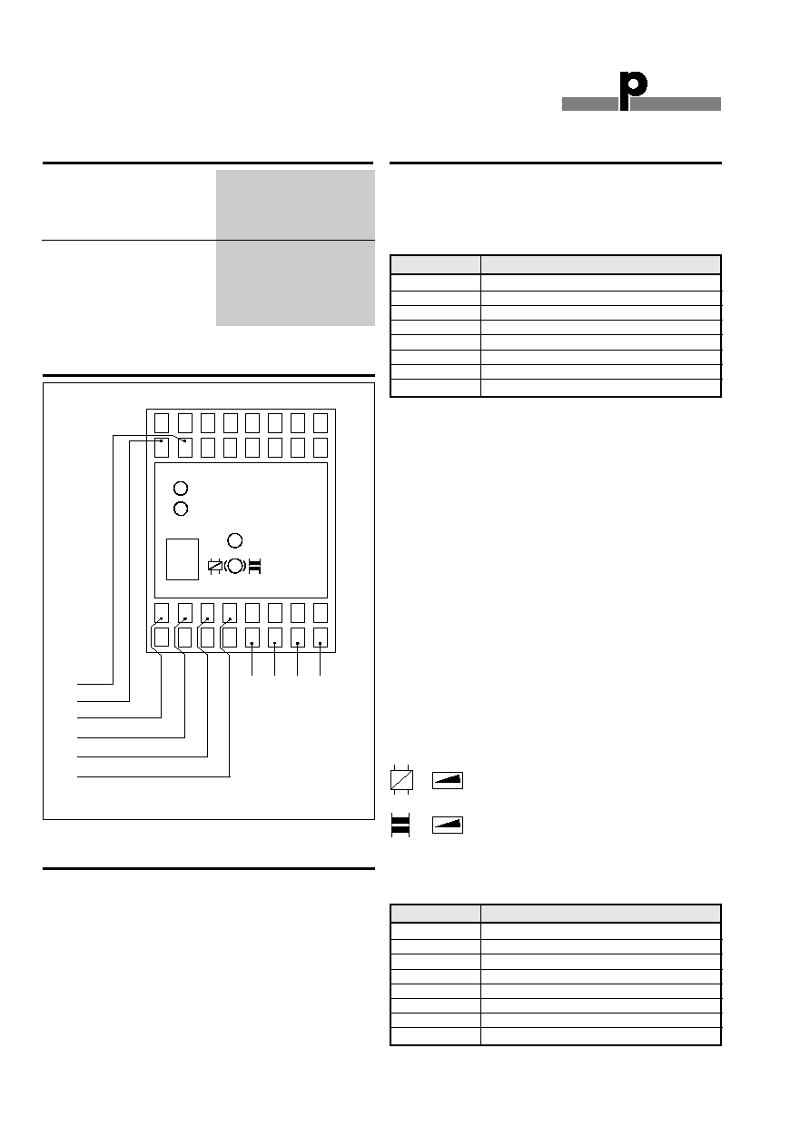
Wiring Diagram
G 4248 4134
Accessories
It is possible to connect up to 10 slave Dimmers (500W/1500W)
to one G 4248 4134.
General Specifications (cont.)
Coding
With the GAP1605 programming unit, each switching chan-
nel can be assigned any adress between A1 and P8 via the
modular socket on the front of the dimmer. The allocation of
the channels is as follows:
Channels 5 and 6 are assigned only at G4248 4134 724.
Functions which are not required should remain uncoded.
The coding of the dimmer can be carried out without either
supply voltage or Dupline signal. It is retained permanently
but may be overwritten at any time.
The channels are configured in such a way at the factory
that they will be switched off in the event of a fault. This
configuration, too, can be changed with the GAP1605.
Setting "1" results in switching on the lighting to 100% after
3 seconds in case of the event of a fault, while setting "0"
does not influence the dimming output (factory setting). If
the value "0" has been selected, the dimmer can be operated
using the push-button at the front panel in the event of a
fault (even without bus signal); the push-button has the
same functionality as channel 2 (Dimming/On/Off).
Putting into service
Commissioning may only be carried out by an authorized,
trained technician. Observe the connection diagram when
installing. All lines to be connected must be dead.
The N-connection is absolutely necessary for the operation
of the dimmer. The desired operating mode should be
selected before connecting the phase, because the switch is
disabled during operation as a safeguard against accidental
resetting.
Although an incorrect setting will result in malfunction, it will
not cause irreparable damage to the dimmer. The following
table shows the allocation of terminals:
Channel
Description
1
Central Off - Lighting scenes 3/4/6
2
Dimming / On / Off
3
Lighting scene 1 (3/5/6)
4
Lighting scene 2 (4/5/6)
5
Ackn. signal dimming output
6
Ackn. signal alarm
7
Not assigned
8
Not assigned
~~
R, C
R, L
Turn to the left:
AC modulation control
Turn to the right: Phase angle control
Terminal
Description
4.4/4.8
Line in/Line out - dimming channel
3.4/3.8
N-conductor input
1.2
Dupline signal conductor + (D +)
1.6
Dupline signal conductor - (D -)
1.3
Control of slave dimmer. Output S -
1.7
Control of slave dimmer. Output S +
2.3
0 VDC (DC -)
2.7
+24 VDC (DC +)
Operating Device
Button with memory in/out/
dimming function
Switch for selection of ne-
gative/positive phase angle
control
Standards
IEC 60669, EN 55022/
EN 50081-1 and EN 55024/
EN 50082-1
Mode of Operation

Du line
Æ
Fieldbus
Installationbus
Specifications are subject to change without notice (20.12.05)
3
Dupline
Æ
is a registered trademark. A product of the CARLO GAVAZZI Group
Mode of Operation (cont.)
Connections between the Dupline signal and the 24 V sup-
ply, or connection to earth potential, will cause malfunctions
and are not permissible. Attention should be paid to the cor-
rect polarity of the supply voltage and the Dupline signal.
In order to meet the requirements for protective low voltage,
VDE 0100, part 410, should be observed and applied during
installation.
Functions and programming
The dimmer is programmed with the GAP1605 programming
unit. Up to five addresses can be programmed, four of which
(IN/OUT 1-4 of the GAP1605) are dedicated to controlling
the dimmer itself (light level) - see the following table "Facto-
ry Settings". The remaining fifth address (IN/OUT 5 of the
GAP1605) is an output signal on the bus and indicating if the
dimmer is activated. The addresses are selected in the con-
figuration software as push button channels.
The five addresses (including one status signal address)
The light levels 3, 4, 5 and 6 can be programmed by combining
2 or 3 addresses. The easiest way is to use the master func-
tion in the Master Generator to set up the address combination.
Factory Settings
*
When the function 100% light level is selected, the addresses must be
activated for more than 3 seconds before the function is initiated.
The shown values are factory settings and thus they are pro-
tected against accidental resetting. Nevertheless, it is possible
to disable the protection to change the default values.
The following steps 1-4 explain how the protection can be
disabled, the values changed, the protection reestablished
and default settings restored.
1. Programming access
a) Activate address 1 for minimum 3 seconds.
b) Continue activation of address 1 and activate
simultaneously address 4 five times with a duration
of minimum 0.5 second for every activation.
Address
Description
1
Turn off
2
Dimmer up/down
(long activation)
Turn on/Turn off
(short activation)
3
Desired light level, see "Factory Settings"
4
Desired light level, see "Factory Settings"
5
Dimmer activated
Inputs
(GAP1605 programming)
Address
1 2 3 4
Long/short
10 % to 100 %
activation
0 %
Turn OFF
Not changeable
Light level 1
55 %
Light level 2
100 %
Light level 3
25 %
Light level 4
40 %
Light level 5
70 %
Light level 6
85 %
100 %*
100 %
Not changeable
Light level
(factory setting)
c) When the light shortly turns off (approx. 0.5 s), the
programming access is open.
2. New light level
a) Open for the programming access according to
1. Programming access.
b) Use address 2 to set the required light level.
c) Activate, for more than 3 seconds, the address
to which the chosen light level is to be allocated.
d) When the light turns shortly off (approx. 0.5 s), the
new parameters are accepted and stored.
Undesirable changes of the programmed parameters
can be avoided by reestablisment of the programming
protection - see 3. Protection.
3. Protection
a) Activate address 1 for minimum 3 seconds.
b) Continue activation of address 1 and simultaneously
activate address 3 five times with a duration
of minimum 0.5 second for every activation.
c) When the light shortly turns off (approx. 0.5 s), the
programming access is closed.
4. Restoring of factory settings
a) Activate address 1 for minimum 1 second.
b) Continue activation of address 1 and simultaneously
activate addresses 3 and 4.
c) When the light shortly turns off (approx. 0.5 s), the
factory settings are restored.
When the factory settings are restored the
programming protection is active.
LED indicators
Front-mounted LEDs indicate the status of the device:
LED
Description
GREEN
Dupline carrier:
"Bus OK"
OFF: Bus fault
ON: Bus is OK
RED
Monitoring:
Alarm
OFF: Status OK
ON, flashing slowly: Overload
ON, flashing fast: Short circuit
G 4248 4134
Dimensions (mm)
H4-housing