Du line
Æ
Fieldbus
Installationbus
Specifications are subject to change without notice (25.10.2006)
1
Dupline
Æ
is a registered trademark. A product of the CARLO GAVAZZI Group
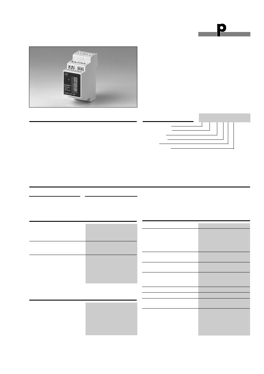
Type: Dupline
Æ
"H2"- Housing
Transmitter
32 Channels
4 inputs
Contact Input
∑ 4 individual counter inputs
∑ Selectable operating mode: Impulse Count or ON-
time Summarizing.
∑ Reset feature
∑ 32 multiplexing addresses
∑ Memory in case of power failure
∑ For DIN-rail mounting
∑ LED-indication for Operational Status
Product Description
Ordering Key
The Counter enables impulse
counting on up to 4 channels
or entry of up to 4 periods of
operation with cyclic transfer
on the Dupline
Æ
Bus.
The device has DIP-switches
for operating mode, for reset
of counter via Dupline
Æ
and
for selection of measuring
range with 2 to 8 decades.
The Two rotary switches
enable individual assignment
of device address.
The counter readings can be
displayed on a Touch Screen
panel or by means of visual-
ization software.
Upon voltage failure, the
counter values will be stored
and be available after return
of the voltage.
Type Selection
Supply
Ordering no.
15-30 VDC
G 4420 7401 724
230 VAC
G 4420 7401 230
G 4420 7401
Input/Output Specifications
Counter
Inputs
4
Type
Contact inputs
Rated current
2 mA @ 24 VDC / Channel
Max. length of cable
5 m
Impulse counting
Resolution
14 Hz
Signal (Pulse/Pause)
40 ms/40 ms
ON-time Summarizing
Resolution
1 s
Accuracy
> 0.5 %
Type G4420 7401
General Specifications
Power ON delay
Undefined
LED-indication for
Degree of protection
IP40
Operational status
On: OK
OFF: Device disturbance or
Power failure
Environment
Operating temperature
-20 to +60∞C
Humidity (non-condensing)
Max. 95% (moisture con-
densation not allowed)
Housing
Distribution-board housing
for DIN-rail mounting acc.
to DIN EN50022
Material
Polycarbonate
Dimensions
36 x 85 x 58 / 2 PD
Terminals
U-clamp terminals
Terminal capacity
Min. 0,4 mm up to max. 2,5 mm
Approvals
CE acc. To EN55022 /
EN50081-1 and EN55024 /
EN50082-1
Supply Specifications
Power Supply
Rated operational voltage
230 VAC ± 15% (IEC 60038)
15 - 30 VDC
Rated operational current
10 mA
1.2
E1
1.6
E2
2.2
E3
2.6
E4
1.3
D-
1.7
D+
1.4
DC-
1.8
DC+
0 1
2
3
4
5
6
7
8
9
A
B
C
D
E
1
2
G 4420 7401 230
Dupline +
Dupline -
0 VDC
+ 24 VDC
1.1
1.5
2.1
2.5
2.3
2.7
2.4 2.8
On-time Summarizing
230 VAC
1.2
E1
1.6
E2
2.2
E3
2.6
E4
1.3
D-
1.7
D+
1.4
DC-
1.8
DC+
0 1
2
3
4
5
6
7
8
9
A
B
C
D
E
1
2
G 4420 7401 230
Counter 1
S0-Output
Counter 1
S0-Output
Counter 1
S0-Output
Counter 1
S0-Output
Dupline +
Dupline -
0 VDC
+ 24 VDC
Counter
1.1
1.5
2.1
2.5
2.3
2.7
2.4 2.8
230 VAC
Du line
Æ
Fieldbus
Installationbus
2
Specifications are subject to change without notice (25.10.2006)
Dupline
Æ
is a registered trademark. A product of the CARLO GAVAZZI Group
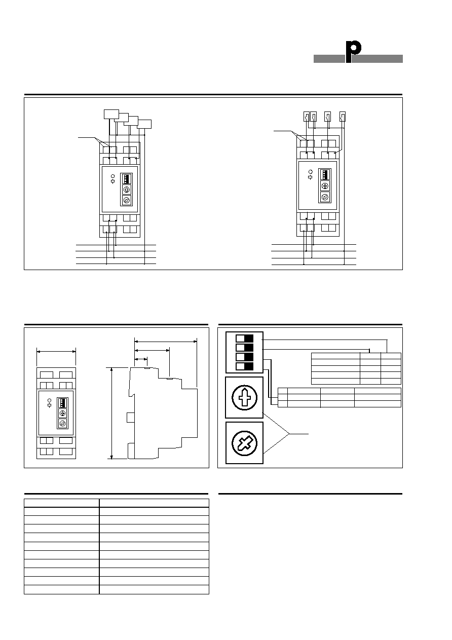
G 4420 7401
Dimensions
58
32
12
85
36
1.2
E1
1.6
E2
2.2
E3
2.6
E4
1.3
D-
1.7
D+
1.4
DC-
1.8
DC+
0 1
2
3
4
5
6
7
8
9
A
B
C
D
E
1
2
G 4420 7401 230
Wiring Diagrams
Dip-switch Settings
0 1
2
3
4
5
6
7
8
9
A
B
C
D
E
1
2
In order to avoid disturbances, the length of the cable between the counter inputs of G4420 7401 and the impulse output
should not exceed 5 m. NOTE: The G4420 7401 724 is pure DC-supplied. The G4420 7401 230 are having the possibility
of two powersupplies. Both a DC and a AC, If using the DC Supply, the minus of the supply is used as common wire
for the inputs of the module.
Terminal
Function
1.2
Counter Input 1
1.6
Counter Input 2
2.2
Counter Input 3
2.6
Counter Input 4
1.3
Dup. Gnd
1.7
Dupline
Æ
Signal
1.4
0 VDC
1.8
+24 VDC
1.1
230 VAC
1.5
230 VAC
Terminal Assignment
ON
1 2 3 4
Measurring range
DIP-3
DIP-4
0 ..........................99
OFF
OFF
0 ......................9999
OFF
ON
0 ................999999
ON
OFF
0 ............99999999
ON
ON
DIP Description
OFF
ON
1 Reset
Disable
Enable
2
Operating mode Impulse Counter ON-time Summarizing
Rotary Switches 1&2. Device address
Accessories
For counting electric energy,
Carlo Gavazzi offers a wide
range of energy meters,
which can be used in con-
nection with Dupline coun-
ters. The below energy
meters can be supplied with a
DIN 43 864 pulse output:
EMI-DINAV81DPX
EM3-DINAV?3?O
EM4-DINAV?3?OXX
WM22-DINAV?3?OXX
SPT90AV???P??XXX
WM2-96AV?3?O1X
WM3-96AV?3?XXXXO1XXX
WM3-96AV?3?XXXXO2R2
WM3-96AV?3?XXXXO2R102
WM3-96AV?3?XXXXO2R204
WM4-96???3?XXXXO1XXX
WM4-96???3?XXXXO2R2
WM4-96???3?XXXXO2R102
WM4-96???3?XXXXO2R204
Du line
Æ
Fieldbus
Installationbus
Specifications are subject to change without notice (25.10.2006)
3
Dupline
Æ
is a registered trademark. A product of the CARLO GAVAZZI Group
G4420 7401 has 4 DIP-switches for selection of Operating
mode and 2 rotary switches for selection of device address.
Selection of device address (rotary switches)
Selection of device address is performed by means of the two
rotary switches at the front. In multiplex mode, up to 32 devices
with 4 channels each (128 counter values) can operate on the
same Dupline
Æ
network simultaneously.
The address selection is deliberately kept simple: all that is
needed is to assign a unique address to the first of the four
channels of G 4420 7401. The following addresses are then
automatically assigned to the three other channels. If several
G 4420 7401 are used, the settings must look as follows:
The 4 counter inputs can be selected individually as follows:
A change of address during operation has immediate effect,
but does not influence the counter value. After the change, the
G 4420 7401 transmits updated values to the new address.
The Dupline
Æ
multiplex operation makes it possible to transmit
several counter or analog values to the same address so that
the number of addresses in use remains relatively low. By
means of a special addressing mechanism, it is possible to
transmit up to 128 signals on channels B2 to B8.
If a device detects the address of one of its channels, it will
transfer the data to the bus in the same cycle. The addresses
used for counting start with C1 and ≠ depending on the mea-
suring range ≠ go up to F8. The address is created as a binary
value.
RESET Feature (Dip-switch 1)
The G 4420 7401 makes it possible to reset each of the four
counter values induvidually via the Dupline-Bus. In order to
prevent unwanted resetting, this function can be disabled for all
channels via Dip-Switch 1.
Dip-switch 1 OFF: Reset Disabled
Dip-switch 1 ON: Reset Enabled
The Reset of a value takes place through address B1. If the
address is set to "1" during the reading of the value, the G 4420
7401 automatically sets the counter value to "0". It is also pos-
sible to reset the respective multiplex address by setting B1 to
"1" and then back to "0".
Operating Mode (DIP switch 2)
It is possible to select operating mode for all channels with DIP
switch 2. Two modes can be selected:
Dip-switch 2 OFF: All channels operates as impulse Count
Dip-switch 2 ON: All channels operates as impulse Count or
ON-time Summarizing
When operating as an impulse counter (position "OFF"), the
G 4420 7401 counts impulses at the inputs of up to 20 Hz.
When DIP switch 2 is set to "ON", G 4420 7401 counts the
operating hours and sums up the time for which the contact
connected to the input is enabled. Min. time is 1 s.
Selection of measuring range DIP switches 3 & 4
DIP switches 3 & 4 make it possible to select measuring ranges
with 2 to 8 digit positions in two steps. If the measuring range
is exceeded, the counter rolls over and starts from zero.
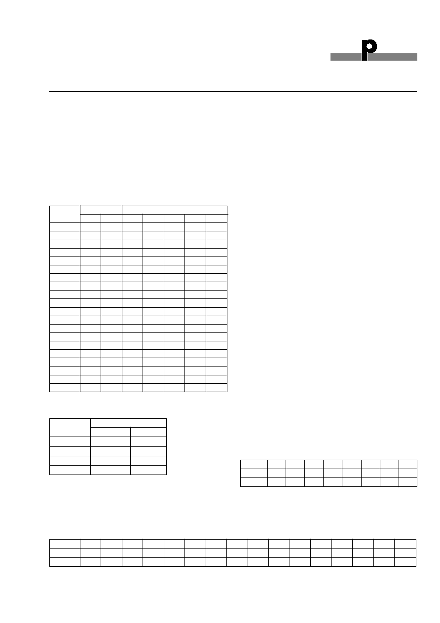
Data channels
Data transmission by G 4420 7401 always starts on the first
address in channel group C. The number of addresses needed
depends on the selected measuring range. The value "59" lies
in the range from 0 ≠ 99 and looks as follows:
The value " 7584" lies in the range from 0 ≠ 9999 and looks as
follows:
Factor
80
40
20
10
8
4
2
1
Channel C1
C2
C3
C4
C5
C6
C7
C8
Value
0
1
0
1
1
0
0
1
Input
Dupline
Æ
Channel
Counter
B7
B8
1
0
0
2
0
1
3
1
0
4
1
1
Device Rotary
Switch
Dupline
Æ
Channel
Address
1
2
B2
B3
B4
B5
B6
0
1
0
0
0
0
0
0
1
1
1
0
0
0
0
1
2
1
2
0
0
0
1
0
3
1
3
0
0
0
1
1
4
1
4
0
0
1
0
0
5
1
5
0
0
1
0
1
6
1
6
0
0
1
1
0
.
.
.
.
.
.
.
.
.
.
.
.
.
.
.
.
14
1
E
0
1
1
1
0
15
1
F
0
1
1
1
1
16
2
0
1
0
0
0
0
17
2
1
1
0
0
0
1
.
.
.
.
.
.
.
.
.
.
.
.
.
.
.
.
27
2
B
1
1
0
1
1
28
2
C
1
1
1
0
0
29
2
D
1
1
1
0
1
30
2
E
1
1
1
1
0
31
2
F
1
1
1
1
1
Mode of Operation
Factor
8000
4000
2000
1000
800
400
200
100
80
40
20
10
8
4
2
1
Channel
C1
C2
C3
C4
C5
C6
C7
C8
D1
D2
D3
D4
D5
D6
D7
D8
Value
0
1
1
1
0
1
0
1
1
0
0
0
0
1
0
0
G 4420 7401