Type: Dupline
Æ
Fuga housing
Transmitter
8 channels
8 inputs
Input type
Du line
Æ
Fieldbus
Installationbus
Specifications are subject to change without notice (26.01.2006)
1
Dupline
Æ
is a registered trademark. A product of the CARLO GAVAZZI Group
Ordering Key
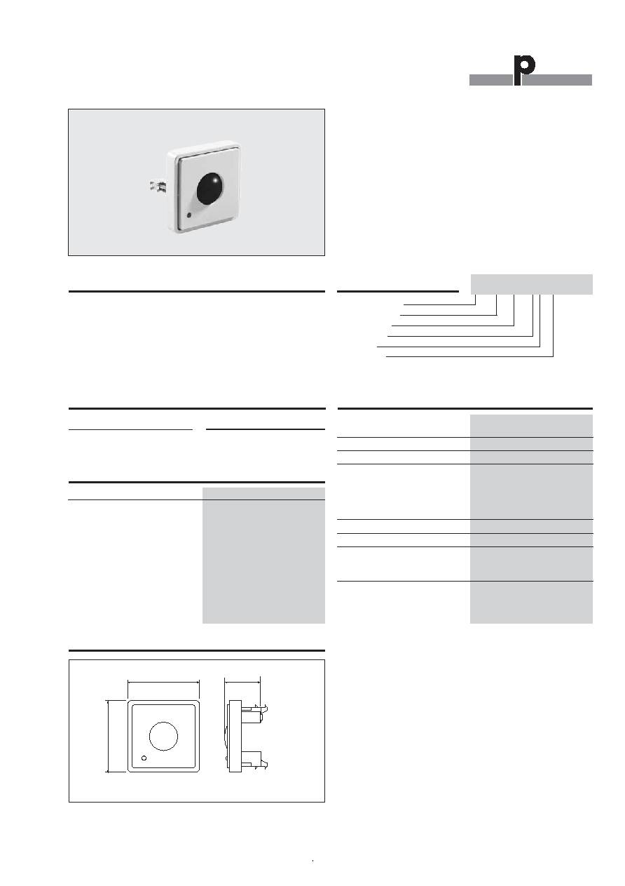
Product Description
∑ IR receiver for B&O light remote control
∑ 8-channel Dupline
Æ
transmitter
∑ Supplied by Dupline
Æ
, no external supply required
∑ Channel coding by GAP 1605
∑ Indoor applications
Type Selection
Supply Specifications
Power supply
Supplied by Dupline
Æ
Consumption
Not activated
3.5 mA
Activated
Typ. 4.9 mA
IR Receiver for B&O
Type G 8185 5533
G 8185 5533
General Specifications
Channel coding
By GAP 1605 and special
cable: GAP-TPH-CAB
No. of channels
8
Enclosure
LKNES FUGA Mechanics
Environment
Degree of protection
IP 20
Pollution degree
3 (IEC 60664)
Operating temperature
0 - 50 ∞C (32 - 122∞F)
Storage temperature
-20 - 70∞C (-4 - 158∞F)
Humidity (non condensing)
20 - 80%
Weight
50 g
Dimensions
Fuga
50 x 50 x 30 mm
(including frame)
Max. wire in terminals
Max. 4 x 0.75 mm
2
Supply
Ordering no.
By Dupline
Æ
G 8185 5533
The IR receiver is designed
and cocecfor B&O remote
controllers with light control
function. By means of the
programming unit CAP 1605
and cable GAP-TPH-CAB,
each og the 8 channels in the
IR receiver can be coded to a
freely selected address. The
IR receiver activates the set
Dupline
Æ
as long as the cor-
responding button on the
B&O remote controller is
activated.
Dimensions
50
50
30*
* + mounting clips

Du line
Æ
Fieldbus
Installationbus
2
Specifications are subject to change without notice (26.01.2006)
Dupline
Æ
is a registered trademark. A product of the CARLO GAVAZZI Group
G 8185 5533
Programming cable
to GAP 1605
GAP-TPH-CAB
Accessories
Mode of Operation
Remote controls capable of
operating the G 8X85 5533
The BEO4 and all BEOLINK
1000 types equipped with a
"light" button can operate
the module.
Controlling G 8X85 5533
If the room is equipped with
only one IR module, activate
(for example on BEO4) the
buttons "Light, 1, GO" to
change the status of the first
output. The buttons 1-8 cor-
respond to the outputs 1-8.
To activate the output, use
the following buttons: GO,
, , and .
For ON/OFF control it is re-
commended to use the GO-
button and for light dimming
one of the four buttons:
,
, and .
When the remote control is
in LIGHT mode, it is possible
to change an output without
use of the LIGHT button.
If the room is equipped with
several modules, a DIP-
switch determines the mod-
ules address. See the follow-
ing chapter.
DIP-switch setting
If only one module is used all
three switches must be OFF
(i.e. positioned towards the
digits on the PCB).
It is possible to operate 4
different modules and DIP-
switches 1 and 2 determine
the module address. See the
table below.
DIP-switch 3 determines
whether 1 (OFF) or several
modules (ON) are in use.
Switch 1
Switch 2
Switch 3
Module address
Buttons
Example of sequence
Don't care
Don't care
OFF
Single module
1 - 8
LIGHT, 1, GO
ON
ON
ON
Module # 0
01 - 08
LIGHT, 0, 1, GO
OFF
ON
ON
Module # 1
11 - 18
LIGHT, 1, 1, GO
ON
OFF
ON
Module # 2
21 - 28
LIGHT, 2, 1, GO
OFF
OFF
ON
Module # 3
31 - 38
LIGHT, 3, 1, GO
Wiring Diagram
D-
D+
Dupline
Æ
NO
1 2 3
Dip-switch
Dot
Programming Cable GAP-TPH-CAB
Programming Adaptor plug to GAP 1605