Specifications are subject to change without notice (04.11.05)
1
Monitoring Relays
∑ 3-phased current metering relay
∑ Measures on current with 3-phased current
metering transformers, type A74-.. ...
∑ Measures if all 3-phase currents are within
set limits
∑ Upper and lower limits separately adjustable
∑ Output: 10 A SPDT relay
∑ For mounting on DIN-rail in accordance with
DIN/EN 50 022
∑ H4-housing
∑ LED-indication for power supply and output ON
∑ AC power supply 2-phases
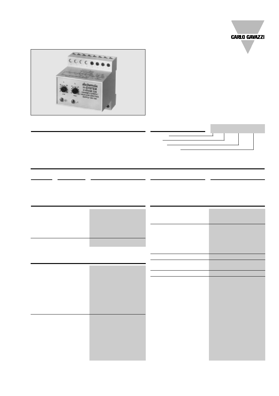
3-phase current metering re-
lay with separate setting of
upper and lower current level.
For DIN-rail mounting. Often
used where a certain applica-
H 475 156 230
tion such as a large mixer has
to be kept within a set current
value in order not to overload
the system.
Type Selection
Input Specifications
Input from current
transformers
A74-.. ...
Terminal 5
red, phase L1
Terminal 6
white, phase L2
Terminal 7
yellow, phase L3
Terminal 8
black
Input voltage
0.4-4 V
p
Plug
Output
Supply: 115 VAC
Supply: 230 VAC
Supply: 400 VAC
Screw
SPDT
H 475 156 115
H 475 156 230
H 475 156 400
terminals
Output
SPDT relay
Rated insulation voltage
250 VAC (rms)
(cont./elect.)
Contact ratings (AgCdO)
µ (micro gap)
Resistive loads
AC 1
10 A/250 VAC (2500 VA)
DC 1
1 A/250 VDC (250 W)
or
10 A/25 VDC (250 W)
Small inductive loads AC 15
2.5 A/230 VAC
DC 13
5 A/24 VDC
Mechanical life
30 x 10
6
operations
Electrical life
AC 1
2.5 x 10
5
operations
(at max. load)
Operating frequency
7200 operations/h
Dielectric strength
Dielectric voltage
2 kVAC (rms) (cont./elect.)
Rated impulse withstand volt. 4 kV (1.2/50 µs) (cont./elect.)
(IEC 60664)
Power supply AC types
Overvoltage cat. III (IEC 60664)
Rated operational voltage
(IEC 60038)
Through term. 22 & 24 115
115 VAC ±15%, 45 to 65 Hz
230
230 VAC ± 15%, 45 to 65 Hz
400
400 VAC ± 15%, 45 to 65 Hz
Voltage interruption
40 ms
Dielectric voltage
2 kVAC (rms) (supply/elect.)
Rated impulse withstand volt.
4 kV (1.2/50 µs) (line/neutral)
(line/line), no direct connec-
tion to electronics
Rated operational power
2.5 VA
Product Description
Ordering Key
Housing
Type
Output
Power supply
3-Phase Max. and Min. Current Control
Type H 475
Output Specifications
Supply Specifications
2
Specifications are subject to change without notice (04.11.05)
H 475
Reaction time
= 0.2 s, worst case reaction
time may be up to 5 x
Indication for
Power supply ON
LED, green
Output ON LED, red
Environment
(IEC 60947-1)
Degree of protection
IP 20 B/front IP40 D (IEC 60529)
Pollution degree
3 (IEC 60664)
Operating temperature
-20∞ to +50∞C (-4∞ to +122∞F)
Storage temperature
-50∞ to +85∞C (-58∞ to +185∞F)
Weight
300 g
CE Marking
Yes
The relay requiring 2-phased
power supply is used with
one of the 3-phased current
metering transformers, types
A 74-10 5, A 74-10 20, A 74-
11 100, A 74-11 500. When
the supply voltage is applied
the relay operates, provided
the current flowing in all 3-
phase cables exceeds the
minimum current of the trans-
formers and phase cables
must be drawn through the
transformer from the same
side.
Mode of Operation
When the power supply is
applied the relay operates
when all 3-phase currents are
within the set levels, and re-
leases when one or more
phase-phase currents ex-
ceed the upper set level or
drop below the set level. The
relay operates again when all
3-phase currents are within
the set levels. Hysteresis on
operate is approx. 2%. The
phase sequence through the
current metering transformer
is arbitrary.
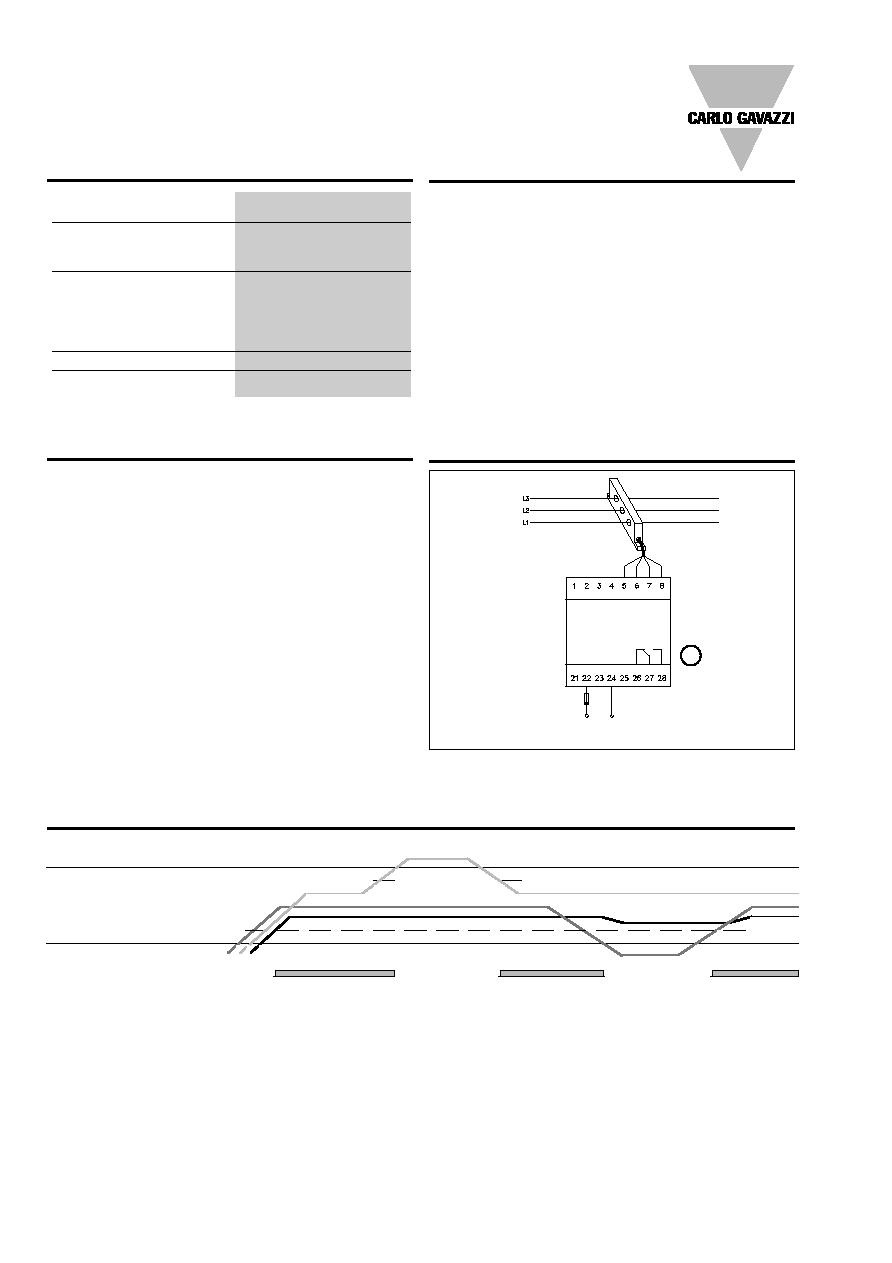
Wiring Diagram
Measuring range
3-phased current metering
transformers measure in the
following 4 ranges:
A 74-10 5 = 0.5- 5 A
A 74-10 20 = 2 - 20 A
A 74-11 100 = 10 - 100 A
A 74-11 500 = 50 - 500 A
Range setting
Left potentiometer:
Lower limit. From 8 to 98% of
nominal max. value for the
current metering transformer
employed.
Range Setting
Right potentiometer:
Upper limit. From 10 to 100%
of nominal max. value for the
current transformer employed.
If the lower limit is set above
the upper limit, the output re-
lay releases and cannot be
activated before the lower limit
is set lower than the upper
limit.
Hysteresis
Max. limit: - 2%
Min. limit: + 2%
Upper limit
Hysteresis
Lower limit
Hysteresis
Relay ON
L1, L2, L3
Operation Diagram
Power supply
H 475
PE = term 8
µ
Term. 5: Red core
Term. 6: White core
Term. 7: Yellow core
Term. 8: Black core
General Specifications