Specifications are subject to change without notice (13.01.03)
1
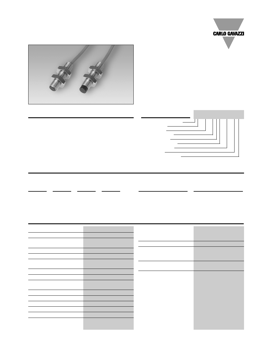
Proximity Sensors Inductive
Extended Range, Stainless Steel Housing
Types IA, DC, M8, 2-wire
∑ Sensing distance: 2 to 4 mm
∑ Flush and non-flush types
∑ Power supply: 10 to 30 VDC
∑ Output: Transistor
∑ Make or break switching
∑ Protection: Reverse polarity, short-circuit and transients
∑ 2 m cable
∑ Diameter: M8
Product Description
in accordance with Euronorm
EN 60 947-5-2.
M8 proximity switch with
extended sensing range in
stainless steel housing. Made
Type Selection
Housing
Body
Connec-
Rated
Ordering no.
Ordering no.
diameter
style
tion
operating
2 wire DC
2 wire DC
dist. (S
n
)
Normally open
Normally closed
M8
Short
Cable
2 mm
1)
IA 08 BSF 02 DO
IA 08 BSF 02 DC
M8
Short
Cable
4 mm
2)
IA 08 BSN 04 DO
IA 08 BSN 04 DC
1)
For flush mounting in metal
2)
For non-flush mounting in metal
Ordering Key
Ind. proximity switch
Housing style
Housing size
Housing material
Housing length
Detection principle
Sensing distance
Output type
Output configuration
IA 08 BSF 02 DO
Specifications
Rated operational volt. (U
B
)
10 to 30 VDC (ripple included)
Ripple
10%
Rated operational current (I
e
)
Continuous
3-100 mA
No-load supply current (I)
1.2 mA
Voltage drop (U
d
)
8 VDC at max. load
Protection
Reverse polarity,
short-circuit, transients
Transient voltage
2 kV/0.5 J
Power ON delay
< 50 ms
Frequency of operating
cycles (f)
2 kHz
Indication
LED, yellow
Repeat accuracy (R)
2 %
Hysteresis (H) (Differential travel) 1 to 20% of sensing distance
Assured operating dist. (S
a
)
0
S
a
0.77 S
n
Effective operating dist. (S
r
)
0.9 x S
n
S
r
1.1 x S
n
Usable operating dist. (S)
0.85 x S
r
S
u
1.15 x S
r
Ambient temperature
Operating
-25∞ to +70∞C (-13∞ to +158∞F)
Storage
-30∞ to +80∞C (-22∞ to +176∞F)
Degree of protection
IP 67 (Nema 1, 3, 4, 6, 13)
Housing material
Body
Stainless steel
Front
Black thermoplastic polyester
Connection
Cable, 2 m, 2 x 0.5 mm
2
,
grey PVC, oil proof
CE-marking
Yes
2
Specifications are subject to change without notice (13.01.03)
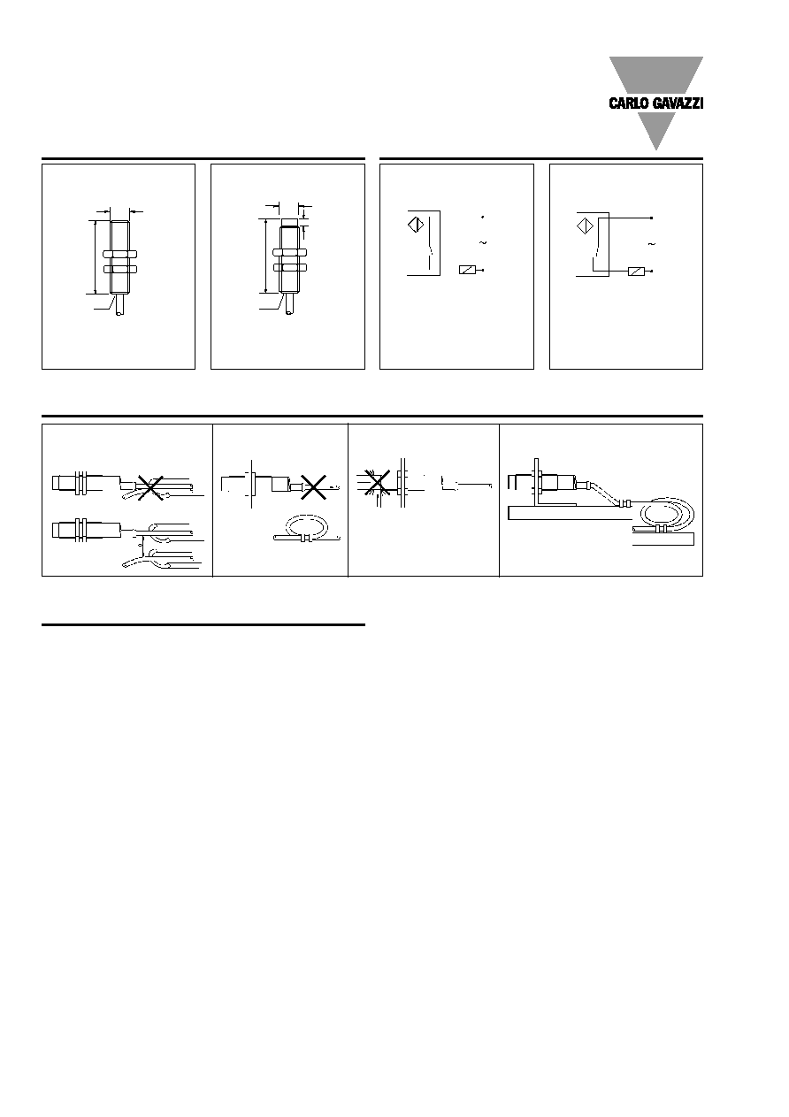
Installation Hints
Relief of cable strain
Protection of the sensing face
Switch mounted on mobile carrier
To avoid interference from inductive voltage/
current peaks, separate the prox. switch pow-
er cables from any other power cables, e.g.
motor, contactor or solenoid cables
Incorrect
Correct
The cable should not be pulled
A proximity switch should not serve as
mechanical stop
Any repetitive flexing of the
cable should be avoided
Power Supplies
Power supplies VDC:
> SS 130/140.
IA, DC, M8, 2-wire
Dimensions
Wiring Diagrams
Make switching (NO)
4
3
BU-
BN+
3
4
BU-
BN+
LOAD
LOAD
Break switching (NC)
M8 x 1
30
LED
IA 08 BSF 02 D.
30
4
LED
M8 x 1
IA 08 BSN 04 D.