Specifications are subject to change without notice (11.08.2006)
1
Housing
Connec- Body
Rated
Ordering no.
Ordering no.
Ordering no.
Ordering no.
diameter tion
style
operating
NPN
PNP
NPN
PNP
distance S
n
Make switching
Make switching
Break switching
Break switching
M12
Cable
Long
2 mm
1)
IA 12 DLF 02 NOLD
IA 12 DLF 02 POLD
IA 12 DLF 02 NCLD
IA 12 DLF 02 PCLD
M18
Cable
Short
5 mm
1)
IA 18 DSF 05 NOLD
IA 18 DSF 05 POLD
IA 18 DSF 05 NCLD
IA 18 DSF 05 PCLD
M30
Cable
Short
10 mm
1)
IA 30 DSF 10 NOLD
IA 30 DSF 10 POLD
IA 30 DSF 10 NCLD
IA 30 DSF 10 PCLD
1)
For flush mounting in metal
� Load Dump protection: SAE & ISO
� Sensing distance: 2 to10 mm
� Flush types
� M12 long housing; M18 & M30 short housing
� Rated operational voltage: 10 - 40 VDC
� Output: DC 200 mA, NPN or PNP
� Make or break switching function
� LED-indication
� Protection: reverse polarity, short circuit, transients
� Cable versions
Product Description
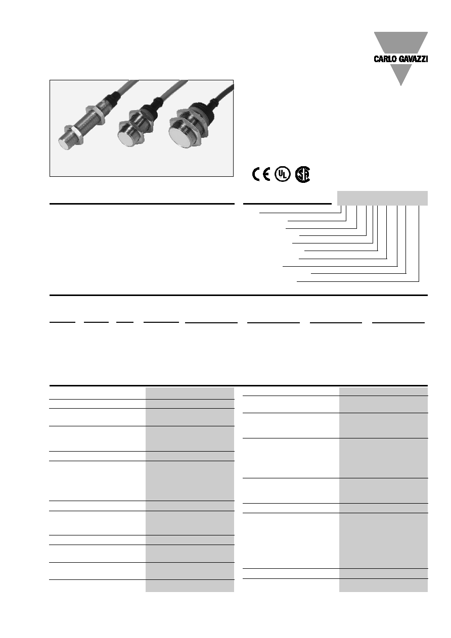
A family of Load Dump pro-
tected inductive proximity
switches in industrial stan-
dard nickel-plated brass
housings. M12, M18 and
M30 types. They are able to
handle applications in vehi-
cles that use battery operated
systems and generates high
voltage transients. Typical
applications: Lift trucks,
garbage trucks etc. Output
are open collector NPN or
PNP transistors. Available
with cable only.
Ordering Key
Type
Housing style
Housing size
Housing material
Housing length
Detection principle
Sensing distance
Output type
Output configuration
Load Dump
Load Dump Proximity Sensors Inductive
Nickel-Plated Brass Housing
Types IA, M12, M18 and M30
Type Selection
IA12DLF02NOLD
Specifications
Repeat accuracy (R)
5%
Differential travel (H)
(Hysteresis)
1 to 15% of sensing dist.
Ambient temperature
Operating
-25� to +70�C (-13� to +158�F)
Storage
-30� to +80�C (-22� to +176�F)
Housing material
Body
Nickel-plated brass
Front
Grey thermoplastic polyester
Backpart
PBTP (black polyester)
Nuts
Nickel-plated brass
Connection
Cable
2 m, 3 x 0.3 mm
2
,
grey PVC,oil proof
Degree of protection
IP 67
Weight (cable/nuts included)
IA 12 .L.
105 g
IA 18 .S.
120 g
IA 30 .S.
185 g
Tightening torque
IA 12
7.0 Nm (x)
15.0 Nm (y)
IA 18
27.5 Nm
IA 30
50.0 Nm
Approvals
UL, CSA
CE-marking
Yes
Rated operational voltage (U
B
) 10 to 40 VDC (ripple incl.)
Ripple
10%
Output current (I
e
)
200 mA @ 50�C
( 150 mA @ 50-70�C)
No load supply current (I
O
)
IA 12 6 mA
IA 18 6 mA
IA 30 6 mA
Voltage drop (U
d
)
Max. 2.5 VDC @ 200 mA
Protection
Reverse polarity, short-
circuit, transients
Load Dump Protection
SAE J11133-11 and
ISO 7637-2 - Test Level 4
Transient voltage
1 kV/0.5 J
Power ON delay (t
v
)
50 ms
Operating frequency (f)
IA12 ..F 02
800 Hz
IA18 ..F 05
800 Hz
IA30 ..F 10
700 Hz
Indication for output ON
LED, yellow
Assured operating
sensing distance (S
a
) 0
S
a
0.81 x S
n
Effective operating
distance (S
r
)
0.9 x S
n
S
r
1.1 x S
n
Usable operating distance (S
u
) 0.9 x S
r
S
u
1.1 x S
r

2
Specifications are subject to change without notice (11.08.2006)
Cable type
C
D
E
F
SW
A
LED
B
Installation Hints
Relief of cable strain
Protection of the sensing face
Switch mounted on mobile carrier
To avoid interference from inductive voltage/
current peaks, separate the prox. switch pow-
er cables from any other power cables, e.g.
motor, contactor or solenoid cables
Incorrect
Correct
The cable should not be pulled
A proximity switch should not serve as
mechanical stop
Any repetitive flexing of the
cable should be avoided
Delivery Contents
� Inductive promimity switch IA..
� 2 nuts NPB
� Packaging: plastic bag
IA, M12, M18 and M30
Dimensions
Type
A
B
C
D
E
F
SW
� mm mm
mm
mm
mm mm
IA 12 DLF 02 .. LD
M12 x 1 x 50
10.7
50
11
5.0
4
17
IA 18 DSF 05 .. LD
M18 x 1 x 30
16.7
30
11.6
15.4
4
24
IA 30 DSF 10 .. LD
M30 x 1.5 x 30
28
30
13.6
15.4
5
36
Wiring Diagrams
+
-
BN
BK
BU
+
-
BN
BK
BU
+
-
BN
BK
BU
+
-
BN
BK
BU
NPN - Make switching
NPN - Break switching
PNP - Make switching
PNP - Break switching