Specifications are subject to change without notice (21.11.03)
1
Housing
Connec- Body
Rated
Ordering no.
Ordering no.
Ordering no.
Ordering no.
diameter tion
style
operating
NPN
PNP
NPN
PNP
distance S
n
Make switching
Make switching
Break switching
Break switching
M12
Cable
Short
2 mm
1)
IA 12 DSF 02 NO
IA 12 DSF 02 PO
M12
Plug
Short
2 mm
1)
IA 12 ASF 02 NOM1
IA 12 ASF 02 POM1
M12
Cable
Long
2 mm
1)
IA 12 DLF 02 NO
IA 12 DLF 02 PO
M12
Plug
Long
2 mm
1)
IA 12 ALF 02 NOM1
IA 12 ALF 02 POM1
M12
Cable
Short
4 mm
2)
IA 12 DSN 04 NO
IA 12 DSN 04 PO
IA 12 DSN 04 NC
IA 12 DSN 04 PC
M12
Plug
Short
4 mm
2)
IA 12 ASN 04 NOM1
IA 12 ASN 04 POM1
IA 12 ASN 04 NCM1
IA 12 ASN 04 PCM1
M18
Cable
Short
5 mm
1)
IA 18 DSF 05 NO
IA 18 DSF 05 PO
M18
Plug
Short
5 mm
1)
IA 18 ASF 05 NOM1
IA 18 ASF 05 POM1
M18
Cable
Long
5 mm
1)
IA 18 DLF 05 PO
IA 18 DLF 05 PC
M18
Plug
Long
5 mm
1)
IA 18 ALF 05 POM1
IA 18 ALF 05 PCM1
M18
Cable
Short
8 mm
2)
IA 18 DSN 08 NO
IA 18 DSN 08 PO
IA 18 DSN 08 NC
IA 18 DSN 08 PC
M18
Plug
Short
8 mm
2)
IA 18 ASN 08 NOM1
IA 18 ASN 08 POM1
IA 18 ASN 08 NCM1
IA 18 ASN 08 PCM1
M30
Cable
Short
10 mm
1)
IA 30 DSF 10 NO
IA 30 DSF 10 PO
M30
Plug
Short
10 mm
1)
IA 30 ASF 10 NOM1
IA 30 ASF 10 POM1
M30
Cable
Long
10 mm
1)
IA 30 DLF 10 PO
IA 30 DLF 10 PC
M30
Plug
Long
10 mm
1)
IA 30 ALF 10 POM1
M30
Cable
Short
15 mm
2)
IA 30 DSN 15 NO
IA 30 DSN 15 PO
M30
Plug
Short
15 mm
2)
IA 30 ASN 15 NOM1
IA 30 ASN 15 POM1
1)
For flush mounting in metal
2)
For non-flush mounting in metal
� Sensing distance: 2 to 15 mm
� Flush and non-flush types
� Long and short body
� Rated operational voltage: 10 - 40 VDC
� Output: DC 200 mA, NPN or PNP
� Make and break switching function
� LED-indication
� Protection: reverse polarity, short circuit, transients
� Cable and plug versions
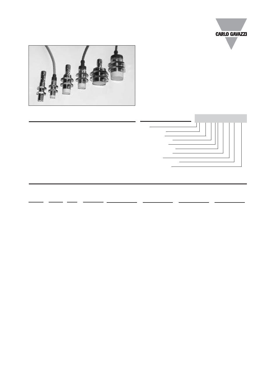
Product Description
A family of inexpensive gen-
eral purpose inductive prox-
imity switches in industrial
standard nickel-plated brass
housings. M12, M18 and
M30 types. They are able to
handle simple applications
where a basic sensor pro-
vides adequate sensing per-
formance. Output are open
collector NPN or PNP tran-
sistors. Available with cable
and M12 plug.
Ordering Key
Type
Housing style
Housing size
Housing material
Housing length
Detection principle
Sensing distance
Output type
Output configuration
Connection type
Proximity Sensors Inductive
Nickel-Plated Brass Housing
Types IA, M12, M18 and M30
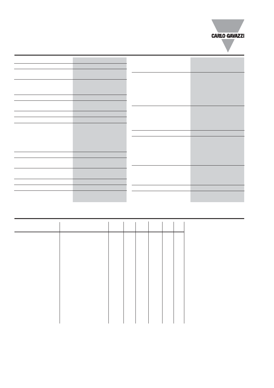
Type Selection
IA12ASF02NOM1
5 years warranty
2
Specifications are subject to change without notice (21.11.03)
IA, M12, M18 and M30
Dimensions
Type
A
B
C
D
E
F
SW
� mm mm
mm
mm
mm mm
IA 12 DSF 02 .O
M12 x 1 x 30
10.7
30
11
5.0
4
17
IA 12 ASF 02 .O M1
M12 x 1 x 30
10.7
30
25.2
4
17
IA 12 DLF 02 .O
M12 x 1 x 50
10.7
50
11
5.0
4
17
IA 12 ALF 02 .O M1
M12 x 1 x 50
10.7
50
25.2
4
17
IA 12 DSN 04 .O
M12 x 1 x 30
10.7
34
11
5.0
4
17
IA 12 ASN 04 .O M1
M12 x 1 x 30
10.7
34
25.2
4
17
IA 18 DSF 05 .O
M18 x 1 x 30
16.7
30
11.6
15.4
4
24
IA 18 ASF 05 .O M1
M18 x 1 x 30
16.7
30
25.0
4
24
IA 18 DLF 05 ..
M18 x 1 x 50
16.7
50
11.6
15.4
4
24
IA 18 ALF 05 .O M1
M18 x 1 x 50
16.7
50
25.0
4
24
IA 18 DSN 08 .O
M18 x 1 x 30
16.7
38
11.6
15.4
4
24
IA 18 ASN 08 .O M1
M18 x 1 x 30
16.7
38
25.0
4
24
IA 30 DSF 10 .O
M30 x 1.5 x 30
28
30
13.6
15.4
5
36
IA 30 ASF 10 .O M1
M30 x 1.5 x 30
28
30
25.0
5
36
IA 30 DLF 10 ..
M30 x 1.5 x 50
28
50
13.6
15.4
5
36
IA 30 ALF 10 .O M1
M30 x 1.5 x 50
28
50
25.0
5
36
IA 30 DSN 15 .O
M30 x 1.5 x 30
28
42
13.6
15.4
5
36
IA 30 ASN 15 .O M1
M30 x 1.5 x 30
28
42
25.0
5
36
Specifications
Ambient temperature
Operating
-25� to +70�C (-13� to +158�F)
Storage
-30� to +80�C (-22� to +176�F)
Housing material
Body
Nickel-plated brass
Front
Grey thermoplastic polyester
Backpart
Plug
NPB
Cable
PBTP (black polyester)
Nuts
NPB
Connection
Cable
2 m, 3 x 0.3 mm
2
,
grey PVC,oil proof
Plug
M12 x 1
Cables for plug (-1)
CONH1A/CONH1O series
Degree of protection
IP 67
Weight (cable/nuts included)
IA 12 .S.
100 g
IA 12 .L.
105 g
IA 18 .S.
120 g
IA 18 .L.
130 g
IA 30 .S.
185 g
IA 30 .L.
195 g
Tightening torque
IA 12
7.0 Nm (x)
15.0 Nm (y)
IA 18
27.5 Nm
IA 30
50.0 Nm
Approvals
UL, CSA
CE-marking
Yes
Rated operational voltage (U
B
) 10 to 40 VDC (ripple incl.)
Ripple
10%
Output current (I
e
)
200 mA @ 50�C
(
150 mA @ 50-70�C)
No load supply current (I
O
)
IA 12
10 mA
IA 18
10 mA
IA 30
10 mA
Voltage drop (U
d
)
Max. 2.5 VDC @ 200 mA
Protection
Reverse polarity,
short-circuit, transients
Transient voltage
1 kV/0.5 J
Power ON delay (t
v
)
50 ms
Operating frequency (f)
IA12 ..F 02
2000 Hz
IA12 DSN 04
2000 Hz
IA18 ..F 05
1500 Hz
IA18 DSN 08
1500 Hz
IA30 ..F 10
700 Hz
IA30 DSN 15
700 Hz
Indication for output ON
LED, yellow
Assured operating
sensing distance (S
a
) 0
S
a
0.81 x S
n
Effective operating
distance (S
r
)
0.9 x S
n
S
r
1.1 x S
n
Usable operating distance (S
u
) 0.9 x S
r
S
u
1.1 x S
r
Repeat accuracy (R)
5%
Differential travel (H)
(Hysteresis)
1 to 15% of sensing dist.
Specifications are subject to change without notice (21.11.03)
3
IA, M12, M18 and M30
Cable type
C
D
E
F
SW
A
LED
B
Plug type
C
D
F
SW A
LEDs
M12 x 1 x 9.5
B
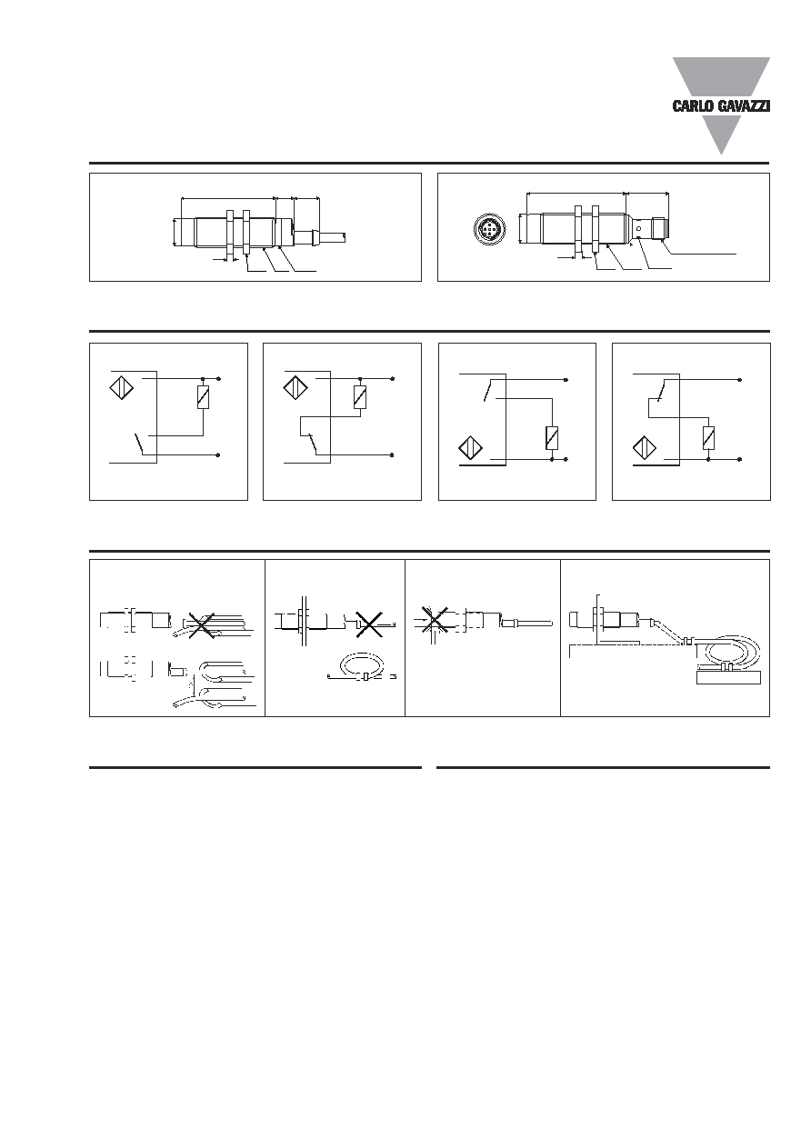
Dimensions (cont.)
Installation Hints
Relief of cable strain
Protection of the sensing face
Switch mounted on mobile carrier
To avoid interference from inductive voltage/
current peaks, separate the prox. switch pow-
er cables from any other power cables, e.g.
motor, contactor or solenoid cables
Incorrect
Correct
The cable should not be pulled
A proximity switch should not serve as
mechanical stop
Any repetitive flexing of the
cable should be avoided
Delivery Contents
� Inductive promimity switch IA..
� 2 nuts NPB
� Packaging: plastic bag
Accessories
M12 connector
CONH1O-A2
(90�, 2 m cable)
CONH1O-A5
(90�, 5 m cable)
CONH1O-S2
(straight, 2 m cable)
CONH1O-S5
(straight, 5 m cable)
Wiring Diagrams
+
-
1 BN
4 BK
3 BU
+
-
1 BN
2 WH
3 BU
+
-
1 BN
4 BK
3 BU
+
-
1 BN
2 WH
3 BU
NPN - Make switching
NPN - Break switching
PNP - Make switching
PNP - Break switching
4
Specifications are subject to change without notice (21.11.03)
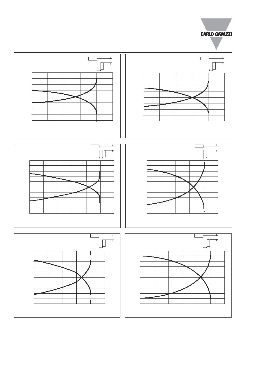
Distance to sensor front (mm)
Distance to sensor center (mm)
0.0
1.0
2.0
3.0
4.0
5.0
6.0
10.0
8.0
6.0
4.0
2.0
0.0
-2.0
-4.0
-6.0
-8.0
-10.0
Distance to sensor front (mm)
Distance to sensor center (mm)
0.0
2.0
4.0
6.0
8.0
10.0
10.0
8.0
6.0
4.0
2.0
0.0
-2.0
-4.0
-6.0
-8.0
-10.0
Sensor
Object
x
y
Sensor
Object
x
y
IA18xSF05..
IA18xSN08..
Distance to sensor front (mm)
Distance to sensor center (mm)
0.0
2.5
5.0
7.5
10.0
12.5
15.0
12.0
9.0
6.0
3.0
0.0
-3.0
-6.0
-9.0
-12.0
-15.0
Distance to sensor front (mm)
Distance to sensor center (mm)
0.0
3.0
6.0
9.0
12.0
15.0
18.0
15.0
12.0
9.0
6.0
3.0
0.0
-3.0
-6.0
-9.0
-12.0
-15.0
Sensor
Object
x
y
Sensor
Object
x
y
IA30xSF15..
IA30xSN15..
Detection Diagrams
Distance to sensor front (mm)
Distance to sensor center (mm)
0.0
0.5
1.0
1.5
2.0
2.5
8.0
6.0
4.0
2.0
0.0
-2.0
-4.0
-6.0
-8.0
IA12xSF02..
Sensor
Object
x
y
Distance to sensor front (mm)
Distance to sensor center (mm)
0.0
1.0
2.0
3.0
4.0
5.0
8.0
6.0
4.0
2.0
0.0
-2.0
-4.0
-6.0
-8.0
Sensor
Object
x
y
IA12xSN04..
IA, M12, M18 and M30