
Specifications are subject to change without notice (20.08.01)
1
Type: Ind. prox. switch
Housing style
Housing size
Housing material
Housing length
Detection principle
Sensing distance
Output type
Output configuration
Types IA, M18, M30
Analogue Voltage Output, Nickel-plated Brass Housing
Proximity Sensors Inductive
∑ Nickel-plated brass housing
∑ Housing diameter: 18 and 30 mm
∑ Sensing distance: 0 - 5 mm, 3.5 - 11 mm
∑ Power supply: 12/17 to 30 VDC
∑ Output: 0-1.6 V, 0-10 V
∑ Protection degree IP67
∑ 2 m PVC cable
Product Description
Inductive proximity sensor
with analogue 0-1.6 or 0-10 V
voltage output. The analogue
signal can be directly con-
nected to measuring sys-
tems. Nickel-plated brass
housing, M18 and M30. Con-
nection with 2 m PVC cable.
Type Selection
Detecting Output
Housing
Connection
Ordering
no.
range
voltage
dimensions
Analogue Voltage Output, PNP
0 - 5 mm
0-1.6 V
M18
Cable, 2 m
IA 18 ALC 05 AH-K
3.5 - 11 mm
0-10 V
M30
Cable, 2 m
IA 30 ASC 11 AK-K
Both types for non-flush mounting
Specifications
Rated operational volt. (U
B
)
IA 18 ALC 05 AH-K
12 to 30 VDC (ripple incl.)
IA 30 ASC 11 AK-K
17 to 30 VDC (ripple incl.)
Ripple
10%
Output voltage
IA 18 ALC 05 AH-K
0 to 1.6 V
IA 30 ASC 11 AK-K
0 to 10 V
No-load supply current (I
o
)
IA 18 ALC 05 AH-K
< 25 mA
IA 30 ASC 11 AK-K
< 33 mA
Load
> 1 k
Detecting range
IA 18 ALC 05 AH-K
0 - 5 mm
IA 30 ASC 11 AK-K
3.5 - 11 mm
Linearity error
IA 18 ALC 05 AH-K
< 5%
IA 30 ASC 11 AK-K
< 1.5%
Temperature drift
IA 18 ALC 05 AH-K
< 10%
IA 30 ASC 11 AK-K
< 4%
Ambient temperature
Operating
IA 18 ALC 05 AH-K
-25∞ to +70∞C (-13∞ to +158∞F)
IA 30 ASC 11 AK-K
0∞ to +60∞C (32∞ to +140∞F)
Storage
-30∞ to +75∞C (-22∞ to +167∞F)
Degree of protection
IP 67 (Nema 1, 3, 4, 6, 13)
Housing material
Nickel-plated brass
CE-marking
Yes
Connection
Cable
2 m, PVC, AWG 22
Ordering Key
IA 18 ALC 05 AH-K
2
Specifications are subject to change without notice (20.08.01)
IA M18, M30
IA 18 ALC 05 AH-K
IA 30 ASC 11 AK-K
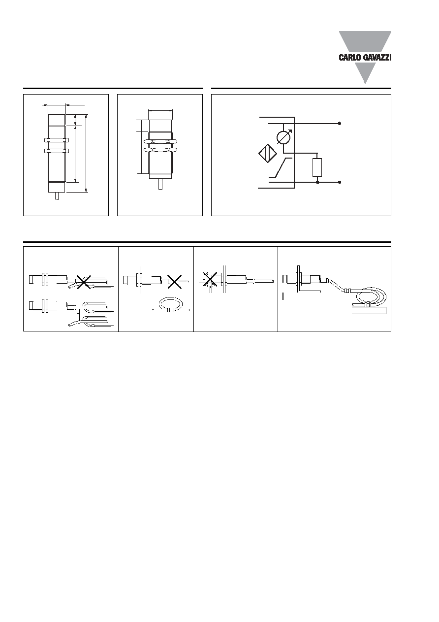
Dimensions
M18 x 1
54
80
12
M30 x 1,5
40
15
Wiring Diagram
+
-
1 BN
3 BU
2 BK
Installation Hints
Relief of cable strain
Protection of the sensing face
Switch mounted on mobile carrier
To avoid interference from inductive voltage/
current peaks, separate the prox. switch pow-
er cables from any other power cables, e.g.
motor, contactor or solenoid cables
Incorrect
Correct
The cable should not be pulled
A proximity switch should not serve as
mechanical stop
Any repetitive flexing of the
cable should be avoided