Specifications are subject to change without notice (10.02.06)
1
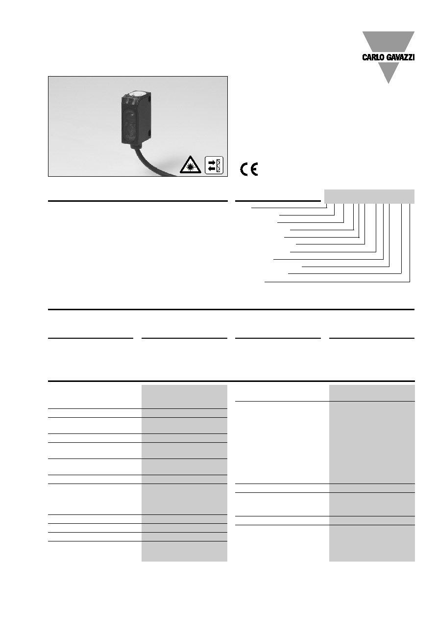
Product Description
The LD32CNP10 sensor family
comes in a compact 12 x 32
x 20 mm reinforced PMMA/
ABS-housing.
The sensors are useful in
applications where high-
accuracy detection as well as
small size is required.
The Teach-In function for
adjustment of the sensitivity
makes the sensors highly
flexible. The output type is
preset (NPN or PNP), and the
output switching function is
programmable (NO or NC).
The small laser spot makes it
possible to detect small
objects very precisely.
∑ Miniature sensor range
∑ Range: 0.1-1 m, with reflector
∑ Sensitivity adjustment by Teach-In programming
∑ Modulated, red laser light 650 nm, polarized (class 2)
∑ Supply voltage: 10 to 30 VDC
∑ Output: 100 mA, NPN or PNP preset
∑ Make and break switching function programmable
∑ LED for output indication and power ON
∑ Protection: reverse polarity, short circuit and transients
∑ Cable and plug versions
∑ Excellent EMC performance
Photoelectrics
Laser, Retro-reflective, Polarized
Type LD32CNP10
Type Selection
Housing
Range
Ordering no.
Ordering no.
W x H x D
S
n
NPN & PNP cable
NPN & PNP plug
Make & break switching
Make & break switching
12 x 32 x 20 mm
1.0 m
LD 32 CNP 10 NPT
LD 32 CNP 10 NPM5T
LD 32 CNP 10 PPT
LD 32 CNP 10 PPM5T
Specifications
Rated operating distance (S
n
)
Up to 1.0 m,
with reflector 51 x 51 mm
(ER5060)
Blind zone
100 mm
Sensitivity
Adjustable by Teach-In
(push button or wire)
Temperature drift
1%/∫C
Hysteresis (H)
(differential travel)
10%
Rated operational volt. (U
B
)
10 to 30 VDC
(ripple included)
Ripple (U
rpp
)
10%
Output current
Continuous (I
e
)
100 mA
Short-time (I)
100 mA
(max. load capacity 100 nF)
No load supply current (I
o
)
25 mA @ 24 VDC
Minimum operational current (I
m
)
0.5 mA
OFF-state current (I
r
)
100 µA
Voltage drop (U
d
)
2.4 VDC @ 100 mA
Protection
Short-circuit, reverse polarity
and transients
Laser protection class
Class 2 - according to
EN60825-1-3/97
Average power
< 1 mW
Pulse width
t = 3 µs
Pulse repetition time
f = 5 kHz
MTBF
> 50'000 h @ T
a
= 40∫C
Light source
Red laser light, 650 nm
Light type
Red, modulated
Sensing angle
< 0.8∫
Ambient light
5,000 lux
Light spot
< 1 mm @ 300 mm
Operating frequency
1000 Hz
Response time
OFF-ON (t
ON
)
0.5 ms
ON-OFF (t
OFF
)
0.5 ms
Power ON delay (t
v
)
300 ms
Output function
NPN and PNP
Preset
NO/NC switching function
Set up by button
Ordering Key
Type
Housing style
Housing size
Housing material
Housing length
Detection principle
Sensing distance
Output type
Output configuration
Connection type
Teach-In
LD32CNP10PPM5T

2
Specifications are subject to change without notice (10.02.06)
Operation Diagram
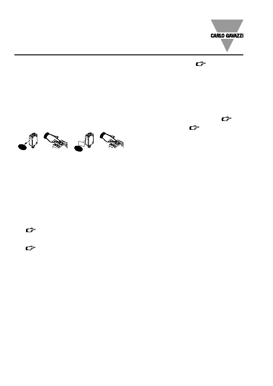
Installation Hints
Relief of cable strain
Protection of the sensing face
Switch mounted on mobile carrier
To avoid interference from inductive voltage/
current peaks, separate the prox. switch pow-
er cables from any other power cables, e.g.
motor, contactor or solenoid cables
Incorrect
Correct
The cable should not be pulled
A proximity switch should not serve as
mechanical stop
Any repetitive flexing of the
cable should be avoided
LD32CNP10
Specifications (cont.)
External Teach (ET)
Same function as button
10 to 30 VDC
Locked (disable teach button)
0 to 2.5 VDC
Operating mode
Not connected
Indication
Output ON
LED, yellow
Signal stability ON and power ON
LED, green
Environment
Installation category
II (IEC 60664/60664A;
60947-1)
Pollution degree
3 (IEC 60664/60664A;
60947-1)
Degree of protection
IP 67 (IEC 60529; 60947-1)
Ambient temperature
Operating
-20 to +60∫ C (-4 to +140∫ F)
Storage
-20 to +80∫ C (-4 to +176∫ F)
Vibration
10 to 55 Hz, 0.5 mm/7.5 g
(IEC 60068-2-6)
Shock
30 g / 11ms, 3 pos, 3 neg
per axis
(IEC 60068-2-6, 60068-2-32)
Rated insulation voltage
500 VAC (rms)
Housing material
Body
ABS, black
Front material
PMMA, red
Connection
Cable
PUR, black, 2 m
4 x 0.14 mm
2
, ÿ = 3.6 mm
Plug
M8, 4-pin
Weight
Cable type: 40 g
Plug type: 10 g
CE-marking
Yes
Wiring Diagrams
+
-
1 BN
4 BK
2 WH
3 BU
ET
NPN
PNP
tv = Power ON delay
Power supply
Object/target present
Break (NC) Output ON
Make (NO) Output ON
Teach input is active when
2 WH wire is connected to
V+ (1 BN).
ET = External Teach
+
-
1 BN
4 BK
2 WH
3 BU
ET
V
V
Specifications are subject to change without notice (10.02.06)
3
Delivery Contents
∑ Photoelectric switch: LD 32 CNP 10
∑ Installation instruction
∑ Packaging: Cardboard box
Signal Stability Indication
Excess gain
Time
150%
100%
70%
Green LED ON
Yellow LED ON
Accessories
LD32CNP10
6
14
5
18.75
3.3
3.3
7.5
30
20
1.2
3.3
Signal level
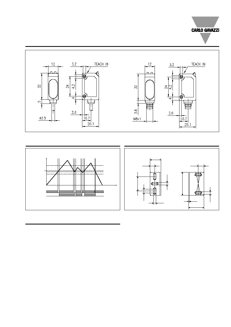
Dimensions
Plug version
Cable version
Mounting bracket APD32-MB3
For further information refer to "Accessories"
4
Specifications are subject to change without notice (10.02.06)
Adjustment
Sensitivity adjustment, with static object (needed for
transparent objects only)
1.
Line up the sensor with the reflector. Yellow LED and
green LED are ON.
2.
Press the button for 3 s until both LED's flash
simultaneously (the first switching point is stored).
3.
Place the object in the detection area.
4.
Press the button for 1 s.
a)
The green LED flashes and stays ON: the
second switching point is stored, and the sensor
is ready to operate.
b)
Both LED's flash simultaneously: the sensor
cannot detect the object, no switching points
are stored.
Adjustment to maximum sensitivity
1.
Line up the sensor with the reflector. Press the button
for 3 s until both LED's flash simultaneously.
2.
Press the button again for 1 s (without object). The
sensor is set to maximum sensitivity.
Sensitivity adjustment, with a running process (needed
for transparent objects only)
1.
Line up the sensor with the reflector. Green LED is ON.
At this stage the status of the yellow LED can be
ignored.
2.
The running process must be the only "object" within
the detection area. Press the button for 3 s until both
LED's flash simultaneously.
3.
Press the button for at least the duration of one pro-
cess cycle.
a)
The green LED flashes and stays ON: both
switching points have been stored, and the sen-
sor is ready to operate.
b)
Both LED's flash simultaneously: the sensor
cannot detect the object, no switching points
are stored.
Programming of make and break switching function
1.
Press the button for 13 s.
Both LED's flash alternately.
2.
Release the button: the green LED flashes.
3.
While the green LED flashes, the output is inverted
each time the button is pressed. This is indicated by
the yellow LED.
When the button is not pressed for 10 s, the current
output function is stored.
The sensor is now ready for operation.
Default setting
1.
Cover light emitter and receiver: Press the button for
3 s, until both LED's flash simultaneously.
2.
Keep light emitter and receiver covered:
Press the button for 1 s.
The sensor is set to maximum sensitivity.
NB! The Teach Input (2 WH) will work similarly to the push
button, active High.
LD32CNP10
3 s
1 cycle
13 s
3 s
1 s
3 s
1 s
1
2
3
4