
26
Specifications are subject to change without notice
Ordering Key
Product Description
Miniature sealed relay accor-
ding to IP 67.
Suitable for automatic
soldering. Produced on fully
automated production line.
Space saving design for
compact packages. Very low
contact noise due to short
bounce time (NO contact)
Type Selection
∑ Miniature size 15 mm high
∑ PCB mounting
∑ 4 kV / 8 mm insulation
∑ Switching capability 8 A / 250 VAC
∑ DC coils 2 to 147 VDC
∑ General purpose, industrial electronics
∑ Sealed according IP 67 standard
∑ 4 different pin layout configurations
∑ Low coil power consumption
M15 M A H 001 8 24VDC
Type
Pin layout configuration
Contact material
Version (H=Sealed)
Contact code
Contact rated current
Coil rated voltage
Pin layout configuration
Contact material
M = 3.5 mm
A = Ag CdO
B = 5.0 mm
B = Ag Ni
F = 2.5 mm
C = Ag CdO, Au plated
E = 3.2 mm / 5.0 mm
D = Ag CdO, gilded
E = AgNi, Au plated
F = Ag, gilded
S = Ag SnO
2
Miniature Power Relays Series M15
Type M15 . . . 100/001
Monostable
Drop out
voltage
VDC
Rated
voltage
VDC
Winding
resistance
± 10%
40
115
160
290
640
1450
2550
10250
31000
0.150
0.250
0.300
0.400
0.600
0.900
1.200
2.400
5.500
3.0
5.0
6.0
8.0
12.0
18.0
24.0
48.0
110.0
Coil Characteristics, DC (20 ∞C)
Contact code
100
001
Contact rating
8 A
8 A
Contact configuration
1 normally open contact
(SPST-NO {1-form A})
1 change over contact
(SPDT-CO {1-form C})
M15
2.00
5.3
3.40
9.0
4.00
10.6
5.40
14.2
8.40
21.2
12.60
31.9
16.00
42.2
33.50
84.7
73.01
147.0
Operating range
Min.
Max.
VDC
VDC

Specifications are subject to change without notice
27
Miniature Power Relay Series M15
Type M15...100/001
Monostable
Temperature Influence
Operating voltages for step exci-
tation. Minimum operating vol-
tage is referred to +20 ∞C/+68 ∞F
ambient temperature; maximum
operating voltage is referred to
+40 ∞C/+104 ∞F ambient tempe-
rature.
Values of minimum and maxi-
mum operating voltage in
respect to ambient tempera-
ture (t) may be obtained
applying following
formulas:
t ∞C
t ∞F
K1
K2
0
32
0.92
1.15
10
50
0.96
1.12
20
68
1.00
1.09
30
86
1.04
1.05
40
104
1.08
1.00
50
122
1.12
0.94
60
140
1.16
0.88
70
158
1.20
0.81
V
min
t
= K1 . V
min 20
V
max
t
= K2 . V
max 40
Insulation
Contact Characteristics
Rating
8 A
Material (standard version)
1)
Ag CdO
Current (for AC)
Rated current
8 A
Max. switching current
10 A
Voltage
Rated voltage
250 VAC - 50 Hz
Max. switching voltage
440 VAC (max 1500 VA)
Max. switching voltage
(VDE 0435)
380 VAC
Power
Max. switch. power
with resistive load in AC
2000 VA
Max. switch. power
with resistive load in DC
See diagram 1
Min. switchng current
3)
100 mA at 24 VDC
Life
Expected life at:
8 A-250 VAC - cos
= 1
100000 cycles
5 A-250 VAC - cos
= 0.4
100000 cycles
Mechan. life at max. switching
frequency of 18.000 cycles/h
30 x 10
6
cycles
General Data
Operating time
at rated voltage
9 ms
Operating bounce time
1 ms
Release time
3 ms
Release bounce time
3 ms
Ambient temperature
2 )
- 40 ∞C to +70 ∞C
Vibration resistance
2,5 mm p.p. 5 ˜ 45 Hz
10 G, 45 ˜ 100 Hz
Shock resistance
10 G, 11 ms
Inside protection
according to IEC 144
IP 67 sealed
Weight
10 g
Working class/type of service
C / Continuous
1)
If required, the contacts can be supplied with flash gilded
silver contacts for storage purpose (24 VDC/10mA), as well
as with gold plated silver contacts for very low switching
levels, in the range of 10 mA and 10 mV.
AgNi contacts for DC loads and AgSnO
2
contacts for heavy
loads are olso available.
2)
Supplying the relay coil at the maximum voltage given in the
table "Temperature Influence", the maximum ambient
temperature value decreases from 70∞ to 40∞C.
3)
Typical value
Insulation Resistance
2 x 10
7
M
at 500 VDC
Test voltage(1 min.)
Open contacts
1000 VAC
Coil/Contacts
4000 VAC
Insulation group
according to VDE 0110
Contact/Coil
IGR
C/660
Open/Contact
IGR
C/250
AC1
(IEC 947-5)
Motor loads
AC 15
DC13
AgCdO
AgSnO
2
250 VAC
250 VAC
24 VDC
115 VAC
250 VAC
115 VAC
250 VAC
M15 001
8A
2.5A
5A
1/8 HP
1/3 HP
1/3 HP
3/4 HP
Special loads - Motor loads
Specifications are subject to change without notice
29
Miniature Power Relay Series M15
Type M15...100/001
Monostable
Use of sealed relays
The M15 relay types are completely
sealed (according to IEC 68 part 2 - 17
{DIN 40046} QC 2 - test).
They are flux proof and are suited for
automated soldering (wave soldering) as
well as for immersion washing.
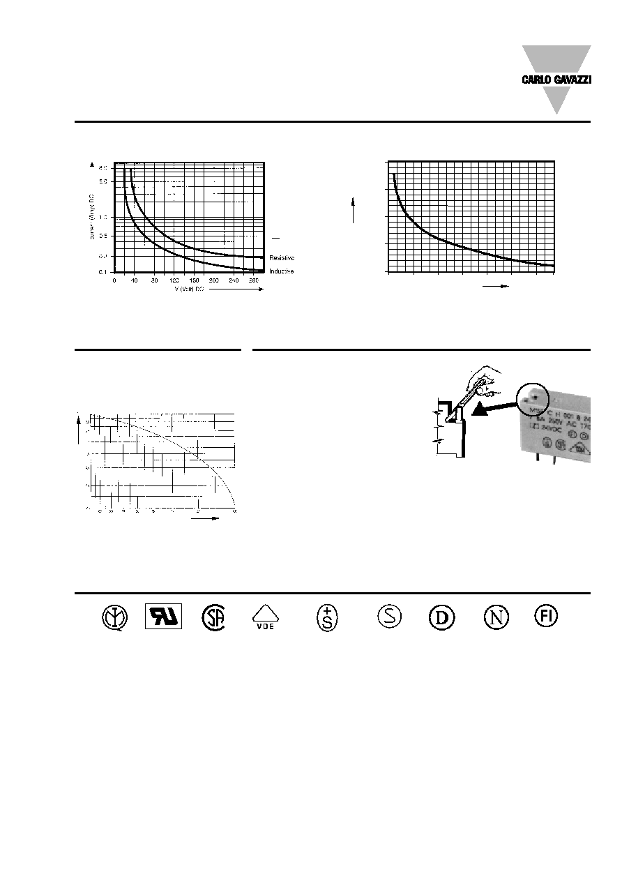
If maximum utilization of the switching
capacity is required, it is recommended
to open the relay after completion of the
soldering/washing process by breaking
out the corresponding pin as indicated.
Product safety
Operations outside the stated ratings
shown in this catalogue may result in a
possible failure or unsafe operating
conditions.
3 Reduction of expected life against
load power factor cos
For all types
Diagrams
Application Hints
Diagrams
0
500.000
0.3
0.6
0.9
1.2
1.5
1.8
2
1.000.000
0
5.000.000
10.000.000
Power (KVA)
Nr
. cycles
1 Max. switching power DC
2 Expected switching cycles/switching current at 250 VAC.
For resistive loads and repetition rate 360 cycles/h.
Approvals
ITALY
U.S.A.
CANADA GERMANY SWITZERLAND SWEDEN DENMARK
NORWAY FINLAND
load power factor (cos
)
Reduction coef
ficent
40ms
L
R
( )
The approvals are not generally
applicable to all relay versions of a
particular type.
For further information please apply for
relevant data sheets ref. 3.84.00.10.X
