Specifications are subject to change without notice (13.02.2006)
1
Photoelectrics
Ordering Key
Type
Emitter
Range
Housing diameter
Optical angle
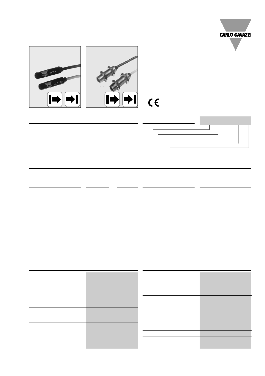
Small through beam photo-
electric switch. Range up to
50 m. 3 beam angles. Wa-
terproof, for dirty environ-
ment, i.e. water, dust, steam
etc. To be used with ampli-
fiers series S142. - S143.
15 m shielded cable, PVC.
ÿ 10 x 42 mm polycarbo-
nate or M12 or M14 stain-
less steel housing. Straight
optical axis.
Product Description
Type Selection
Housing
Rated
Optical
Ordering no.:
Ordering no.:
diameter
operating
angle
Emitter
Receiver
dist. (S
n
)
ÿ 10 mm
5 m
2∞
MOFT 5
MOFR
20 m
2∞
MOFT 20
20 m
5∞
MOFT 20-5
MOFR-5
20 m
8∞
MOFT 20-8
MOFR-8
50 m
2∞
MOFT 50
M12
5 m
2∞
MOFT 5-M12-2
MOFR-M12-2
5 m
5∞
MOFR-M12-5
5 m
8∞
MOFR-M12-8
20 m
2∞
MOFT 20-M12-2
20 m
5∞
MOFT 20-M12-5
20 m
8∞
MOFT 20-M12-8
50 m
2∞
MOFT 50-M12-2
M14
20 m
8∞
MOFT 20-M14-8
MOFR-M14-8
∑ Built-in lens: 2∞, 5∞ or 8∞
∑ Range: 5 m, 20 m or 50 m
∑ Modulated infrared light
∑ High immunity to ambient light
∑ For amplifier series S142. and S143.
∑ Degree of protection IP 66/IP 67
∑ For harsh environment
∑ High penetration power
∑ 15 m shielded PVC cable
∑ ÿ 10 mm polycarbonate housing or M12 or
M14 stainless steel
Specifications Emitter
Specifications Receiver
Rated operational volt. (U
e
)
3 V, (square wave)
supplied by amplifier
Supply current (I
O
)
MOFT 5
10 mA
MOFT 20
15 mA
MOFT 20-5 50 mA
MOFT 20-8 50 mA
MOFT 50
50 mA
Light source
GaAIAs LED, 880 nm
Light type
Infrared, modulated
Optical angle
± 2∞, ± 5∞, ± 8∞
Indications
On amplifier
Protection
Short-circuit, reverse polarity
Rated operational volt. (U
e
)
8 VDC supplied by amplifier
R
source
470
Supply current (I
O
)
11 mA
Sensitivity
Adjustable on amplifier
Optical angle
± 2∞,± 5∞, ± 8∞
Ambient light
10,000 lux (sensitivity ±5%)
Note: The actual range will be
within ±5% of the set range at
an ambient light of 10,000 lux
Operating frequency (f)
See amplifier data
Response time (t
OFF
& t
ON
)
See amplifier data
Power ON delay (t
v
)
See amplifier data
Indications
On amplifier
Protection
Short-circuit, reverse polarity
Types MOFT, MOFR
Through-beam for Separate Amplifier
MOF T 20-M12-2
2
Specifications are subject to change without notice (13.02.2006)
MOFT, MOFR
General Specifications
Environment
Overvoltage category
III (IEC 60664/60664A; 60947-1)
Pollution degree
3 (IEC 60664/60664A; 60947-1)
Degree of protection
IP 66/IP 67 (IEC 60529; 60947-1)
Temperature
Operating
-20∞ to +60∞C (-4∞ to +140∞F)
Storage
-40∞ to +80∞C (-40∞ to +176∞F)
Vibration
10 to 150 Hz, 0.5 mm/7.5 g
(IEC 60068-2-6)
Shock
2 x 1 m & 100 x 0.5 m
(IEC 60068-2-6)
Dielectric voltage
500 VAC (rms)
Housing material
Polycarbonate, black
Connection cable
Emitter
Grey, 15 m oilproof PVC,
ÿ 4 mm, 1 x 0.25 mm
2
,
shielded
Receiver
Black, 15 m oilproof PVC,
ÿ 4 mm, 1 x 0.25 mm
2
,
shielded
Weight (cable incl.)
347 g emitter
347 g receiver
CE-marking
Yes
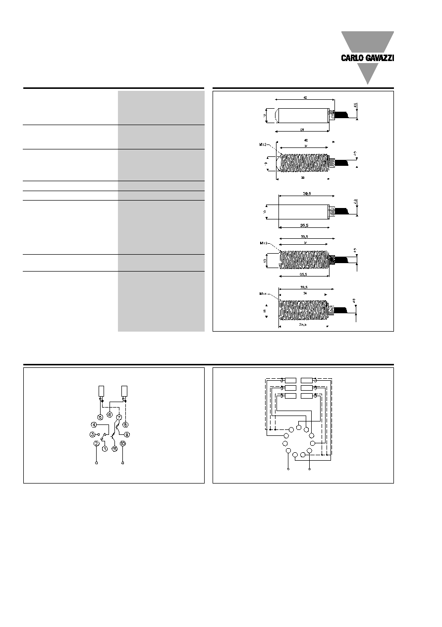
Dimensions
Wiring Diagrams
Emitter
(grey cable)
Receiver
(black cable)
(+)
(-)
Output NPN
Alarm output NPN
Power
supply
8∞ types
Power Supply
8
9
10
11
7
6
5
4
3
1
2
Rx 1
Rx 2
Rx 1
Rx 3
Tx 1
Tx 2
Rx 1
Tx 3
S142....
S143....
2∞ and 5∞ types
Specifications are subject to change without notice (13.02.2006)
3
Delivery Contents
∑ MOFT.. and MOFR
∑ All M12-types: 2 pcs. M12 nuts
∑ All M14-types: 2 pcs. M14 nuts
∑ Packaging: Plastic bag, emitter and receiver packed
separately
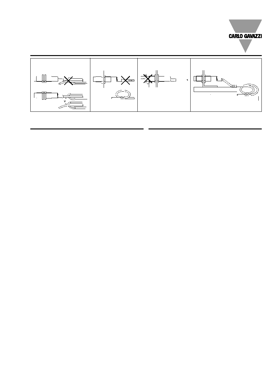
Installation Hints
Relief of cable strain
Protection of the sensing face
Switch mounted on mobile carrier
To avoid interference from inductive voltage/
current peaks, separate the prox. switch pow-
er cables from any other power cables, e.g.
motor, contactor or solenoid cables
Incorrect
Correct
The cable should not be pulled
A proximity switch should not serve as
mechanical stop
Any repetitive flexing of the
cable should be avoided
MOFT, MOFR
Accessories
∑ Mounting bracket MB-M01