Specifications are subjected to change without notice (09.06.06)
1
Power supply
24 VAC -15/+10% 50-60Hz /
24 VDC -15/+10%
Power consumption
< 5 VA / 5 W
Input current/voltage
70 mA @ 24 VDC
Safety outputs
2 NO
Auxiliary outputs
--
Safety output switching
AC 230/240 VAC/8A/1380VA
voltage /current /capability
DC 300 V/6A/1380 VA
Safety output
contact fuse protection
5 A fast or 4 A delayed
Insulation voltage
2.5 KV for signal parts;
4.0 KV for safety output parts:
Pollution degree 2
Overvoltage category III
Electrical Specifications
Lift door unlocking and cabin levelling safety module
NA12DLIFT
∑ Certified according to the Lift Directive
and EN 81-1, /-2, EN 12015 and EN 12016
∑ Redundant circuit
∑ Force guided relay contacts
∑ Dual channel input
∑ 2 NO safety outputs
∑ Failure diagnosis by LEDs
∑ Feedback circuit for external contactors monitoring
∑ Possibility to connect mechanical or magnetic
switches for lift cabin position monitoring
∑ Automatic or manual start
∑ Approval: TÐV
Ordering Key
Lift door unlocking and lift cab-
in levelling safety module,
designed according to Lift
Directive 95/16/CE and to
safety circuits requirements of
EN 81-1, /-2, EN 12015 and
Product Description
EN 12016 Standards.
The module is provided with
safety outputs with force guid-
ed relay contacts, and feed-
back circuit. Suited for applica-
tions of risk category 4.
Housing
Application
Controlled Devices
Safety Outputs
Safety Category
Specific Version
Delay on energisation
150 ms
Delay on de-energisation
25 ms
Channel simultaneity
Operating temperature
-20∞C ... + 65∞C
Storage temperature
-25∞C ... + 65∞C
Time Specifications
Environmental Specifications
Protection degree terminals
IP 20
Protection degree housing
IP 40
Housing material
Polyamid PA 6.6
Housing type
22.5 mm housing models
Mounting
DIN rail
Max cross section
of external conductors
2,5 mm
2
flexible wire
2.5 mm
2
rigid wire
Dimensions
22.5 x 99 x 114 mm
Weight
200 g
Mechanical Specifications
NA12 D LIFT
2
Specifications are subjected to change without notice (09.06.06)
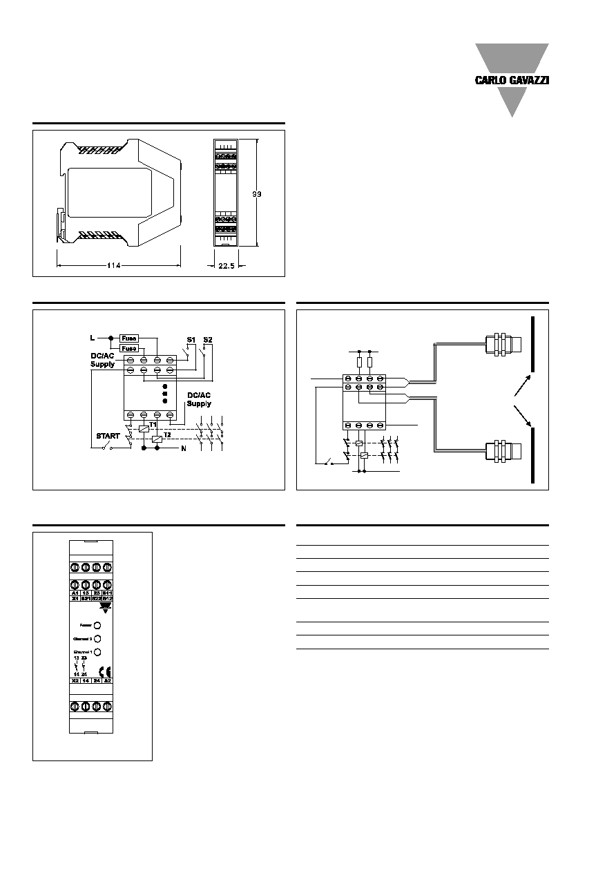
Dimensions
NA12DLIFT
Wiring Diagrams
Application
GND / 24Vac
24 Vdc / Vac
T2
T1
START
N
L
Ext Fuses
Z1
Upper control switch
(Closed contact if operated)
Z2
Lower control switch
(Closed contact if operated)
Actuator magnets
NA1/2-D LIFT
Connection Sample
Terminal
Function/Connection
A1
+24 VDC or AC supply
A2
GND or AC supply
S11-S12
First input channel (NO)
S21-S22
Second input channel (NO)
X1-X2
Feedback and Reset
circuit input
13-14
First safety output (NO)
23-24
Second safety output (NO)
Connections
Front NA12DLIFT
NA12DLIFT
NA12D
LIFT
NA12DLIFT