
Specifications are subjected to change without notice (31.08.06)
1
Power supply
NA13D
24 VAC/DC ± 10%
NA13D110CG 110 VAC ± 10%
NA13D230CG 230 VAC ±10%
Power consumption
4 VA / 4 W
Safety outputs
3 NO
Auxiliary outputs
1 NC
Contact ratings
Resistive loads
AC1
6 A @ 230 VAC
DC12
6 A @ 24 VDC
Small inductive loads AC15
3 A @ 230 VAC
DC13
2.5 A @ 24 VDC
Contact fuse protection
5 A fast or 4 A slow
Insulation voltage
Pollution degree: 2
Overvoltage Category:
3 / 250 V
24 VAC/DC
xxx AC
Supply to input
none
4 kV 1.2/50µs
Supply to output
4 kV 1.2/50µs 4 kV 1.2/50µs
Input to output
4 kV 1.2/50µs 4 kV 1.2/50µs
Electrical Specifications
Type Selection
Emergency Stop and Safety Gate Modules
NA13D
∑ Safety Category 4 according to EN 954-1
∑ Category 0 Emergency Stop
∑ 3 NO safety outputs
∑ 1 NC auxiliary output
∑ 24 VAC / VDC, 110 VAC or 230 VAC power supply
∑ Single/dual channel
∑ Automatic or manual reset
∑ Self monitoring
∑ Failure diagnosis by LEDs
∑ Approvals: TÐV
NORD
,
C
UL
US
Ordering Key
Emergency Stop and Safety
Gate modules according to
EN 60204-1, EN 292-1/-2,
EN 418 and EN 1088.
This family of safety module
in Safety Category 4,
Product Description
includes 24 VAC/VDC, 110
VAC or 230 VAC.
Every model is characterized
by dual channel input and
safety output contacts with
force guided relay outputs.
Housing
Application
Controlled Devices
Safety Outputs
Safety Category
Power Supply
Power supply
24 VAC/VDC
110 VAC
230 VAC
References
NA13D
NA13D110CG
NA13D230CG
Delay on energisation
< 150 ms
Delay on de-energisation
< 30 ms
Channel simultaneity
Operating temperature
-25∞C ... + 55∞C
Storage temperature
-25∞C ... + 65∞C
Time Specifications
Environmental Specifications
Protection degree terminals
IP 20
Protection degree housing
IP 40
Housing material
Polyamid PA6.6
Housing type
22.5 mm housing models
Mounting
DIN rail
Max cross section
2.5 mm
2
rigid wire
of external conductors
2.5 mm
2
flexible wire
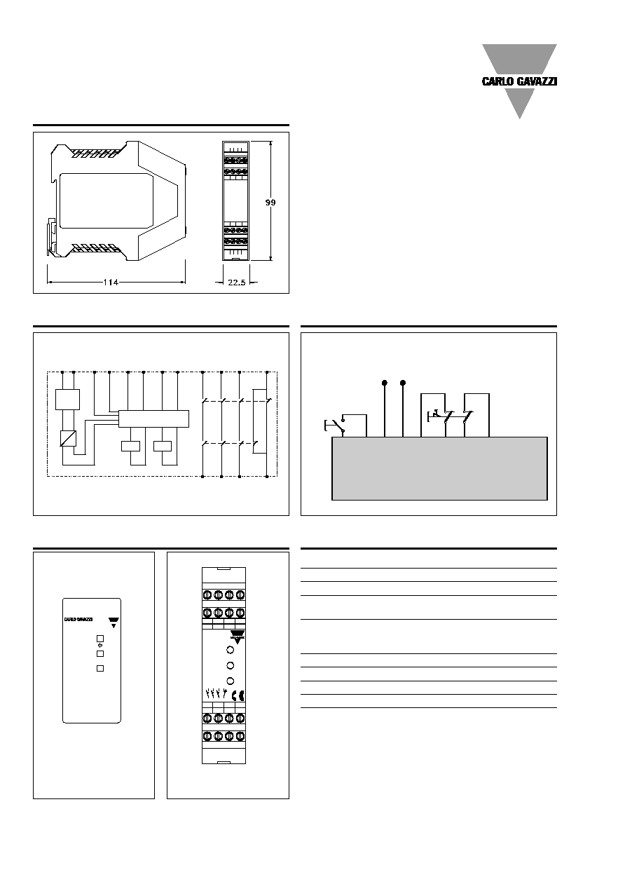
Dimensions
22.5 x 99 x 114 mm
Weight
NA13D
170 g
NA13D230CG, NA13D110CG 238 g
Mechanical Specifications
NA13 D 230
2
Specifications are subjected to change without notice (31.08.06)
Dimensions
NA13D
Wiring Diagrams
Application
Trasf.
K1
K1
A1 A2
S33 S34 S11
S21
S12
S22
K2
-
+
AC
DC
Control Logic
13
33
14
34
23
24
41
42
K2
S34
S33
A2
(-)
A1
(+)
E-STOP
S21 S22 S11 S12 13 23 33 41
14 24 34 42
START
POWER
SUPPLY
Connection Sample
Dual Channel Emergency Stop
Terminal Function
Connection
A1
+24 VDC or AC supply
A2
GND or AC supply
S11-S12
First input channel (E-STOP
or Safety Switch Channel 1)
S21-S22
Second input channel
(E-STOP or Safety Switch
Channel 2)
S33-S34
START (automatic o manual)
13-14
First safety output (NO)
23-24
Second safety output (NO)
33-34
Third safety output (NO)
41-42
Auxiliary output (NC)
Connections
CH2
CH1
N
A
1
3
D
E
m
e
r
g
e
n
c
y
s
t
o
p
m
o
d
u
l
e
S34 S33 S12
A1
S22 S11 A2
23
33
41
13
S21
24
34
42
14
Power
Channel 2
Channel 1
13 23 33 41
A1
S33 S12
S34
13
14
23
24
33
34
41
42
S21 S22 S11 A2
14
34
24
42
NA1/3-D/230
NA13D
NA13D110CG
NA13D230CG
NA13D230