Specifications are subjected to change without notice (12.06.06)
1
Power supply
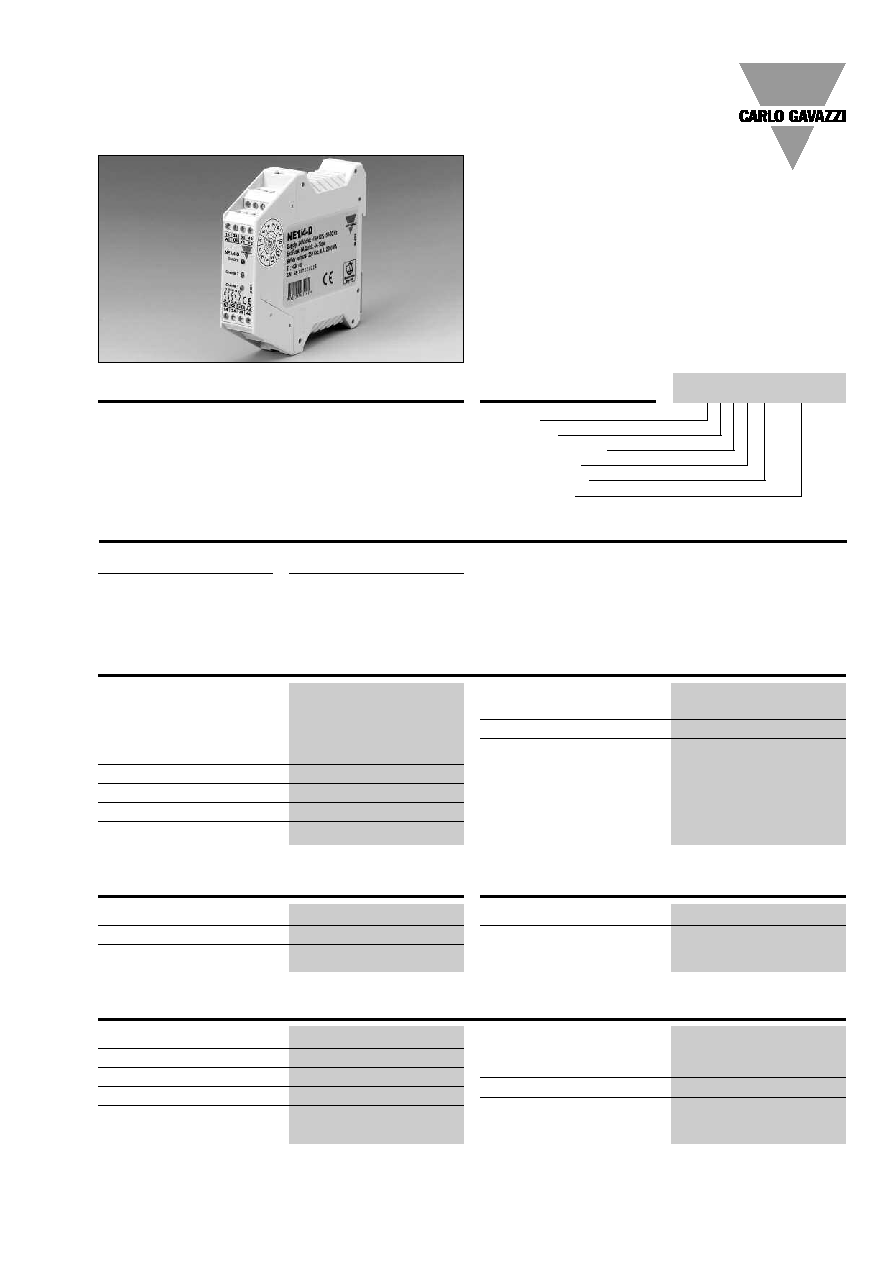
NE14D
24 VAC ≠15/+10% 50-60 Hz
24 VDC ≠15/+10%
NE14D110CG 110 VAC ≠15/+10% 50-60 Hz
NE14D230CG 230 VAC ≠15+10% 50-60 Hz
Power consumption
4 VA /4 W
Input current/voltage
150mA @24VDC
Safety outputs
4 NO
Auxiliary outputs
1 NC Relay
Switching voltage/ 24 VDC, 230 VAC
current /capability 6 A / 2000 VA
Contact fuse protection
6 A fast or 4 A delayed
Insulation voltage
Pollution degree: 2
Overvoltage Cat.: 3/250 V
Basis insulation: Overvoltage
category: 3/250 V
Electrical Specifications
Type Selection
Extension Modules
NE14D
∑ 4 NO safety outputs
∑ 1 NO feedback output
∑ 24 VAC / VDC, 110 VAC or 230 VAC power supply
∑ Suitable for application up to safety category 4
according to EN 954-1
∑ Approvals: TÐV
NORD
, UL
Ordering Key
Extension module according to EN
60204-1, EN202/1 and /2, EN 418,
EN 1088 and EN 954-1. The zero
delay extension modules increase
the number of safety outputs. They
must be used in conjunction with
Product Description
a safety module and allow to keep
the same safety category. They
also provide a NC feedback out-
put to control the internal force
guided relay integrity
Housing
Application
Controlled Devices
Safety Outputs
Safety Category
Power Supply
Power supply
24 VAC/VDC
110 VAC
230 VAC
References
NE14D
NE14D110CG
NE14D230CG
Delay on energisation
150 ms
Delay on de-energisation
< 30 ms
Channel simultaneity
Operating temperature
-25∞C ... + 55∞C
Storage temperature
-25∞C ... + 65∞C
Time Specifications
Environmental Specifications
Protection degree terminals
IP 20
Protection degree housing
IP 40
Housing material
Polyamid PA6.6
Housing type
22.5 housing models
Mounting
DIN rail
Max cross section
of external conductors
2.5 mm
2
flexible wire
2.5 mm
2
rigid wire
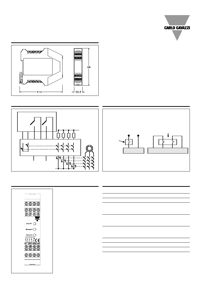
Dimensions
22.5 x 99 x 114 mm
Weight
NE14D
170 g
NE14D110CG, NE14D230CG
240 g
Mechanical Specifications
NE14 D 230
2
Specifications are subjected to change without notice (12.06.06)
Dimensions
NE14D
Wiring Diagrams
Application
A1
A2
13
23
33
14
24
34
GND/Vac
GND/Vac
Power
supply
Power
supply
M
M
L
L
EXT.
FUSES
EXT.
FUSES
MASTE R SAFETY REL AY
MASTER SAFETY REL AY
U1
K1
K21 U22
SAFET Y
OUTPUT S
SAFET Y
OUTPUT S
33
34
N
N
Y2
Y1
FEEDBACK
LOOP
FEEDBACK
LOOP
K1
U1
U22
K21
Dual Channel
A2
A1
Power suppl y
1 N.O. Safety
Contact
from
Master Relay
Single Channel
2 N.O. Safety Contacts
from Master Relay
Connection Sample
Terminal Function
Connection
A1
+24 VDC or AC supply
A2
GND or AC supply
U1-K1
First input channel (N.O.
Safety contact from the
master relay)
K21-U22
Second input channel (N.O.
Safety contact from the
master relay)
Y1-Y2
FEEDBACK output
(to connect to the master
relay)
13-14
First safety output (N.O.)
23-24
Second safety output (N.O.)
33-34
Third safety output (N.O.)
43-44
Fourth safety output (N.O.)
Connections
NE14D