
Specifications are subject to change without notice (08.06.06)
1
Safety Modules
Product Description
Ordering Key
Housing
Function
Auxiliary outputs
Safety outputs
Safety category
Power supply
Terminals
Start/Reset type
∑ Safety Category 4 according to EN 954-1
∑ Category 0 Emergency Stop (EN 60204-1)
∑ 2 x 6 A NO safety outputs (NES02D)
∑ 3 x 6 A NO safety outputs and 1 x 6 A NC auxiliary out-
put (NES13D)
∑ Automatic / manual or monitored manual reset
∑ Single / double channel operations
∑ LED indication for outputs status and power supply ON
∑ Connection by fixed or detachable terminals
∑ For mounting on DIN-rail in accordance with DIN/EN
50 022
∑ 22.5 mm Euronorm housing
Type Selection
Auxiliary
Safety
Terminals
Start/Reset type
Supply: 24 VAC/DC
outputs
outputs
2 NO
Screw, fixed
Automatic / Manual
N ES 0 2 D B24 S A
2 NO
Screw, fixed
Monitored manual
N ES 0 2 D B24 S C
2 NO
Screw, detachable
Automatic / Manual
N ES 0 2 D B24 D A
2 NO
Screw, detachable
Monitored manual
N ES 0 2 D B24 D C
1 NC
3 NO
Screw, fixed
Automatic / Manual
N ES 1 3 D B24 S A
1 NC
3 NO
Screw, fixed
Monitored manual
N ES 1 3 D B24 S C
1 NC
3 NO
Screw, detachable
Automatic / Manual
N ES 1 3 D B24 D A
1 NC
3 NO
Screw, detachable
Monitored manual
N ES 1 3 D B24 D C
Function
2 NO, voltage free
Input current
NES02D
Terminals S11-S21
max 50 mA
Terminals S12-S22
max 60 mA
Switching
max 470 mA
NES13D
Terminals S11-S12
max 60 mA
Terminals S21-S22
max 50 mA
Switching
max 470 mA
Emergency Stop and Safety Gate
Types NES02D, NES13D
Input specifications
Safety outputs
Category 4 (EN 954-1)
NES02D
2 NO (13-14, 23-24)
NES13D
3 NO (13-14, 23-24, 33-34)
Auxilary output
NES13D
1 NC (41-42)
Rated insulation voltage
250 VAC (rms)
Contact ratings (AgSnO
2
)
2 µm Au
Resistive loads
AC1
6 A @ 230 VAC
DC12
6 A @ 24 VDC
Small inductive loads AC15
3 A @ 230 VAC
DC13
2.5 A @ 24 VDC
External contact fuse
protection
5 A fast, 4 A slow
Mechanical life
> 10
7
operations
Electrical life
> 10
5
operations
Dielectric strength
Dielectric voltage
4 kVAC (rms)
Output Specifications
N ES 0 2 D B24 S A
Emergency Stop and Safety
Gate modules according to
EN 60204-1, EN 292-1/-2, EN
418 and EN1088.
This family of safety module
in
Safety Category 4,
includes fixed screw and
detachable screw as well as
automatic/manual or moni-
tored manual restart ver-
sions.
Screw, fixed
Screw, detachable
Delay ON energisation
< 150 ms
Delay ON de-energisation
< 30 ms
Channel simultaneity
during outputs closing
Infinite
Input operating to START
operating delay
NES...C
> 500 ms
Time Specifications

2
Specifications are subject to change without notice (08.06.06)
NES02D, NES13D
Mode of Operation
The safety modules NES02D
and NES13D monitor E-Stop
pushbutton and limit swich
devices, according to
98/37/CE Machinery Direc-
tive.
If the unit is correctly sup-
plied and the input terminals
are closed (i.e. E-Stop not
pushed), the module is
enabled to close the safety
outputs and the external
contactors can be ener-
gized.
When the input terminals are
open (i.e. E-Stop pushed)
the module is not enabled to
close the safety outputs and
the external contactors can
not be energized.
Automatic START
Provided that the terminals
X1 and X2 (NES02...A) or
S33 and S34 (NES13...A) are
connected, the safety out-
puts close and the auxiliary
output opens (NES13...A) as
soon as both S1 and S2
switches are closed.
The relevant CH1 and CH2
LED turn on.
Releasing even one input
contact (S1 and/or S2)
forces immediately the safe-
ty outputs to open and the
auxiliary output (NES13...A)
to close.
A new operating cycle is
possible only after releasing
both input contacts and then
operating them again.
Manual START
Provided that both S1 and
S2 switches are closed, the
safety outputs close and the
auxiliary
output opens
(NES13...A) as soon as the
NO START pushbutton is
pushed [connecting X1 and
X2 (NES02...A) or S33 and
S34 (NES13...A)]
A new operating cycle is
possible only after releasing
both input contacts, closing
them again and pushing the
START button.
Monitored manual START
The monitored manual
START versions (NES...C)
work as described in the
previous paragraph (Manual
START) except for a mini-
mum delay of 500 ms from
the closed status of the
input contacts to the push-
ing of the START button.
If the input terminals get
closed with the START
switch already closed, the
safety outputs don't close
and the auxiliary doesn't
open (NES13...C): it is nec-
essary to release the START
button and the input con-
tacts before starting a new
cycle, then operate the input
contacts and finally, after at
least 500 ms, operate the
START button.
So if the NO START button
gets welded, the outputs
don't close anymore.
Indication for
Power supply ON
LED, green
Output relays ON
LED, green (CH 1, 2)
Environment
(EN 60529)
Degree of protection
IP 30
Pollution degree
2
Operating temperature
-25 to 65∞C, R.H. < 95%
Storage temperature
-30 to 65∞C, R.H. < 95%
Mimimum protection degree
of the installation location
IP 54
Housing dimensions
22.5 x 99 x 114 mm
Weight
Approx. 200 g
Screw terminals
Tightening torque
Upper terminals
Max. 0.5 Nm
Lower terminals
Max 0.8 Nm
Approvals
C
UL
US
, TUV (NES13 only)
CE Marking
Yes
EMC
Electromagnetic Compatibillity
Immunity
According to EN 61000-6-2
Emission
According to EN 61000-6-3
General Specifications
Power supply
Overvoltage cat. III
Rated operational voltage
(IEC 60664)
through terminals:
A1, A2
24 VAC -15% / +10%,
50 to 60 Hz
24 VDC -15% / +10%
Short circuit protection
Internal PTC
Dielectric voltage
DC supply
AC supply
Supply to input
none
none
Supply to output
4 kV
4 kV
Input to output
4 kV
4 kV
Rated operational power
max 5 VA
Supply Specifications
Specifications are subject to change without notice (08.06.06)
3
NES02D, NES13D
24
23
A1
S21
S11
A2
X1
X2
S12
S22
14
13
L
N
L (+)
N (-)
E-STOP
START
S1 S2
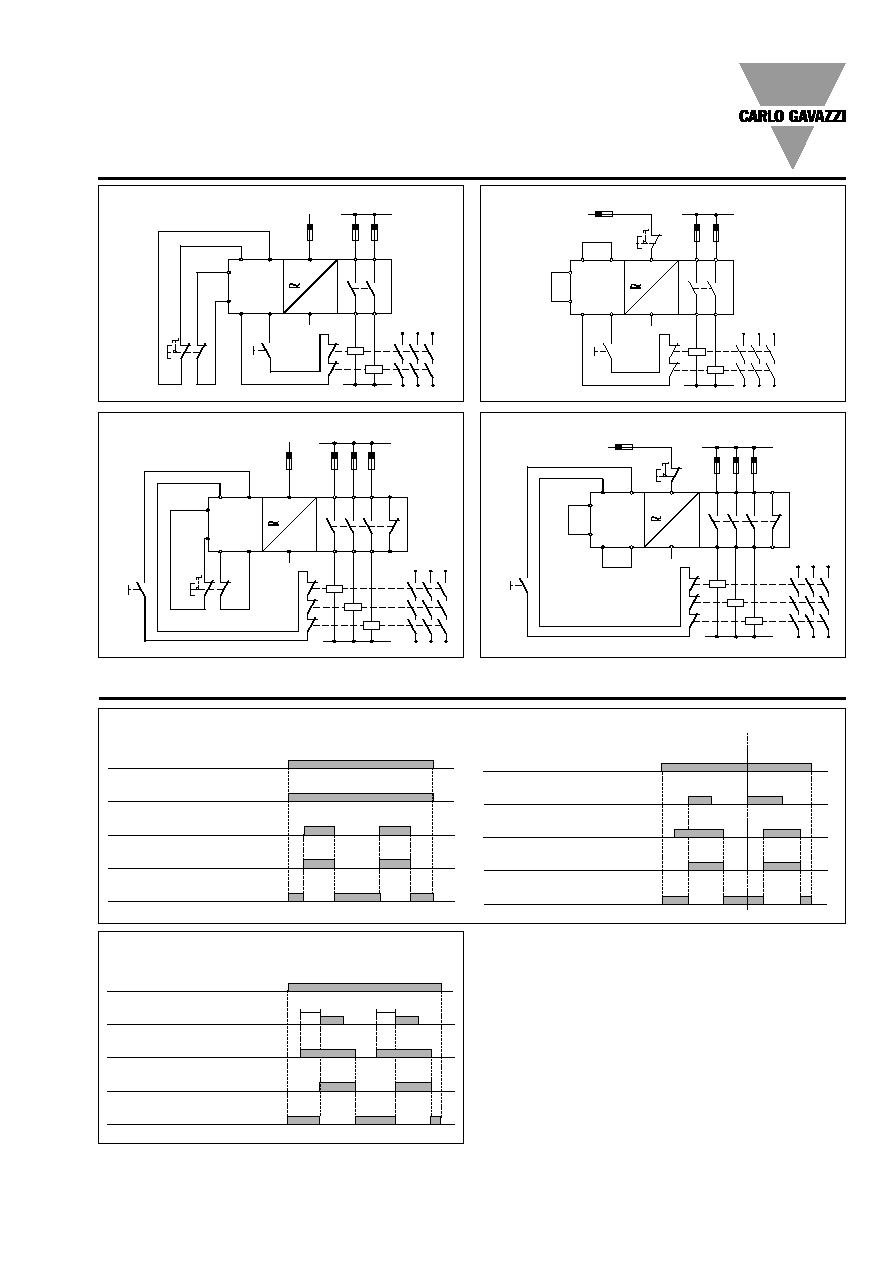
Wiring Diagrams
24
23
A1
S21
S11
A2
X1
X2
S12
S22
14
13
L
N
L (+)
N (-)
S1
E-STOP
START
Double channel - NES02D
Single channel - NES02D
24
23
A1
S34
S33
A2
S11
S12
S21
S22
14
13
L
N
L (+)
N (-)
E-STOP
START
S2 S1
33
34
41
42
24
23
A1
S34
S33
A2
S11
S12
S21
S22
14
13
L
N
N (-)
START
33
34
41
42
L (+)
S1
E-STOP
Double channel - NES13D
Single channel - NES13D
Operation Diagrams
Automatic Start
Power suppy
Reset/Start
Inputs
Safety outputs
Closed
Open
Auxiliary output (NES13D)
ON
OFF
Closed
Open
Closed
Open
Closed
Open
NES02D...SA, NES02D...DA
Manual Start
Input circuit closes
before start circuit
Input circuit closes
after start circuit
Power suppy
Reset/Start
Safety outputs
Inputs
Auxilary output (NES13D)
Closed
Open
ON
OFF
Closed
Open
Closed
Open
Closed
Open
NES13D...SA, NES13D...DA
> 500ms
> 500ms
Monitored Manual Start
Power suppy
Reset/Start
Inputs
Safety outputs
Auxiliary output (NES13D)
Closed
Open
ON
OFF
Closed
Open
Closed
Open
Closed
Open
NES02D...SC, NES02D...DC
NES13D...SC, NES13D...DC

4
Specifications are subject to change without notice (08.06.06)
NES02D, NES13D
Dimensions
Versions with fixed terminals
Versions with detachable terminals