
Specifications are subject to change without notice (26.10.99)
1
Model
Measurement
Power supply
Control output (Out 1)
Alarm output (Out 2)
∑ 4-dgt multi-range µP-based PID controller
∑ Temperature measurements in ∞C or ∞F
∑ All software functions selectable by key-pad
∑ PID, ON/OFF and neutral zone selectable controls
∑ Autotuning, direct or reverse PID control and dynamic
setpoint capability
∑ One relay or SSR control output
∑ One independent alarm setpoint (on request)
∑ Front size: 48 x 48mm
Product Description
Ordering Key
PDI40 T1 DRX
4-dgt multi-range µP-based
controller for temperature
measurements in ∞C or ∞F and
for process signals.
Input from thermoresistance
or thermocouple, PTC, 0/4
to 20mA or 0 to 10VDC. Any
parameter is fully programm-
able by user-friendly key-pad.
The PDI 40 includes auto-
tuning, direct or reverse PID
control and dynamic setpoint
capability. The housing is easy
to mount and ensures a
degree of protection of IP 54.
Temperature Controls
Single Loop PID-Controllers
Type PDI 40
Type Selection
Measurements
T1:
TC inputs: J, K, S
T2:
RTD inputs:
Pt100, Ni100
T3:
PTC input: KTY81
C1:
4 to 20 mA DC
C2:
0 to 20 mADC
V1:
0 to 10 VDC
Power supply
A:
24 VAC, -10% +10%,
50/60 Hz
1)
B:
48 VAC, -10% +10%,
50/60 Hz
1)
C:
115 VAC, -10% +10%,
50/60 Hz
1)
D:
230 VAC, -10% +10%,
50/60 Hz (standard)
E:
120 VAC, -10% +10%,
50/60 Hz
1)
F:
240 VAC, -10% +10%,
50/60 Hz
1)
3:
24 VDC, -10% +10%
with galvanic insulation
1)
Control output (Out 1)
R:
Relay
0:
SSR (12VDC)
Alarm output (Out 2)
X:
None
R:
Relay
0:
SSR (12VDC)
Accuracy
RTD (Pt100, Ni100)
(@ 25∞C ± 5∞C, R.H.
60%)
± 0.5% f.s., ± 1 dgt
TC (J, K, S)
(@ 25∞C ± 5∞C, R.H.
60%)
± 0.5% f.s., ± 1 dgt
PTC (RTY81, 990
@25∞C)
(@ 25∞C ± 5∞C, R.H.
60% )
± 0.5% f.s., ± 1 dgt
Process Signals (20mA, 10V)
(@ 25∞C ± 5∞C, R.H.
60% )
± 0.5% f.s., ± 1 dgt
Temperature drift
RTD
± 150 ppm/∞C
TC
± 150 ppm/∞C
PTC (KTY 81, 990
@25∞C)
± 150 ppm/∞C
Process signals
± 150 ppm/∞C
Sampling rate
1 time/second
Display
7-segment LED, h 12 mm
Max. and min. indication
RTD/TC/PTC
Depending on range and type
of the temperature probe
Process signals
Max. 7000 (700,0),
Min. -999 (-99.9)
Input Specifications
1)
On request
2
Specifications are subject to change without notice (26.10.99)
Compensation
RTD
For 3-wire connections, line
resistance up to 10
TC
Cold junction, within the tem-
perature range from 0 to 55∞C
Input RTD ranges
Probe: Pt100
-200∞C/-328∞F to+600∞C /+1112∞F
-99.9∞C/∞F to +600.0∞C/+999.9∞F
Probe: Ni100
-50∞C/-58∞F to +150∞C/+302∞F
-50.0∞C/-58.0∞F to+150.0∞C/+302.0∞F
Input PTC ranges:
-50∞C/-58∞F to +150∞C/+302∞F
Probe: KTY81 (990
@ 25∞C) -50.0∞C/-58.0∞F to +150.0∞C/+302.0∞F
Output Working
Direct (cooling) or reverse (heating)
Type of output
Relay: 8A-AC1, 3A-AC3,
250 VAC, 100.000 cycles
SSR: 12 VDC/max. 12 mA
Insulation
Relay output: 2000 V
rms
from
output to: measuring input,
AC power supply input.
SSR output: no insulation from
output to measuring input.
2000 V
rms
from output to
AC power supply input.
Alarm output
1 (on request)
Output types
Alarm, ON/OFF, neutral zone
Alarm functions
Up alarm or down alarm
Setpoint adjustment
0 to 100% of the input range
Limits of setpoint adjustment
Programmable minimum and
maximum values
ON/OFF control parameters
Programmable hysteresis
within the whole measuring
range
Programmable activation
time delay (0 to 500 s)
Neutral zone control
Programmable dead band
within the whole measuring
range
Output working
Direct (cooling) or reverse
(heating)
Type of output
Relay: 8A-AC1, 3A-AC3,
250 VAC, 100.000 cycles
SSR: 12 VDC/max. 12 mA
Insulation
Relay output: 2000 V
rms
from
output to measuring input,
AC power supply input.
SSR output: no insulation from
output to measuring input.
2000 V
rms
from output to
AC power supply input.
Output combinations
- only one control output (Out 1)
type: ON/OFF, PID;
- one independent control
output (Out 1) with additional
alarm output: up, down alarm;
- two dependent ON/OFF
control outputs;
- one ON/OFF control output (Out 1)
with dependent relative or
absolute alarm output:
up, down alarm;
- one control output with additional
control output (dead band) to
carry out the neutral zone control
Control output
1 (standard)
Control types
PID, ON/OFF
Setpoint adjustment
0 to 100% of the input range.
Limits of setpoint adjustment
Programmable minimum
and maximum values
PID control parameters
Programmable proportional
band within the whole input
range (1 or 0.1 resolution);
Programmable manual reset
within the whole input range;
Programmable integral time
(0 to 3600 s);
Programmable derivative
time (0 to 3600 s);
Programmable cycle time
(1 to 500 s)
ON/OFF control parameters
Programmable hysteresis
within the whole input range;
Programmable activation time
delay (0 to 500 s)
Neutral zone control
Programmable dead band within
the whole input range (available
only if the 2nd output is present)
PDI 40
Output Specifications
Input TC ranges
Probe: TC-J
0∞C/+32∞F to +800∞C/+1472∞F
Probe: TC-K
0∞C/+32∞F to +1200∞C/+2192∞F
Probe: TC-S
0∞C/+32∞F to +1600∞C/+2912∞F
Input process signal ranges
-999 to 7000
-99.9 to 700.0
Key-pad
3 Keys: "S" to enter into the
programming procedure;
"UP/DOWN" for parameter
selection; "S" + "UP/DOWN"
for value programming
Input Specifications (cont.)
Dynamic setpoint (see fig. 4)
- Action only on 1st output,
automatic increase of the
set-point up to the pro-
grammed one
- Half band programming (drb)
(0 to 100% of the input range)
over which the dynamic
set-point is active
Software functions
- step increase (dSI) parameter,
programmable from 0 to
100% of the input range
- time interval (dSt) between
two step increases pro-
grammable from 1 to 3600 s
Specifications are subject to change without notice (26.10.99)
3
AC supply
24 VAC, 48 VAC, 115 VAC,
120 VAC, 230 VAC, 240 VAC,
-10%+10%, 50/60 Hz
Insulation
2000 V
rms
from power
supply input to: measuring
input, relay output
DC supply
24 VDC, ±10%
Insulation
500 V
rms
from power supply
input to:
measuring input, relay output
Power consumption
5 VA
Operating temperature
From 0∞ to +55∞C
(R.H. < 90% non-condensing)
Storage temperature
From -10∞ to +60∞C
(R.H. < 90% non-condensing)
Insulation reference voltage
300 V
rms
to earth
Autotuning
Activation of autotuning
feature or manual program-
ming of the PID parameters
Diagnostics
The display flashes when
the limits of the displayed
range are exceeded.
Over-range: EEEE
Under-range: - - - -
Burn-out
TC
Opening of the probe connec-
tion, EEEE indication
RTD /PTC/mA/V
Opening of the probe connec-
tion, EEEE indication
Probe short-circuit,
- - - - indication
Outputs
In case of error the outputs
are de-activated
PDI 40
Software Functions (cont.)
Supply Specifications
General Specifications
Scaling factor
programming of the lower
limit of the displayed scale
(only mA/V input) connected
to 0 mA/V or 4 mA, programm-
ing of the higher limit of
the displayed scale (only
mA/V input) connected to
20 mA/10 V.
Offset programming value:
from ≠999 to 999, selection
of decimal point activation
(1 or 0.1), ∞C/∞F engineering
unit selection, least digit
approximation
Dielectric strength
3750 V
rms
for 1 minute
Noise rejection
NMRR
40 dB, from 40 to 60 Hz
CMRR
100 dB, from 40 to 60 Hz
EMC
EN 50 081-1, EN 50 082-1
Safety standards
EN 60730-1
Connector
Fast-on 6,3 mm
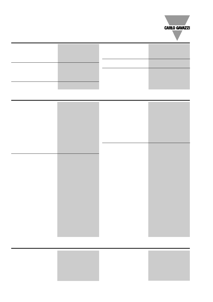
Housing
Dimensions
48 x 48 x 107 mm
Material
ABS,
self-extinguishing: UL 94 V-0
Degree of protection
IP 54 with gasket
Weight
Approx. 250 g
Approvals
CE
Dimensions
Terminal Board
4
Specifications are subject to change without notice (26.10.99)
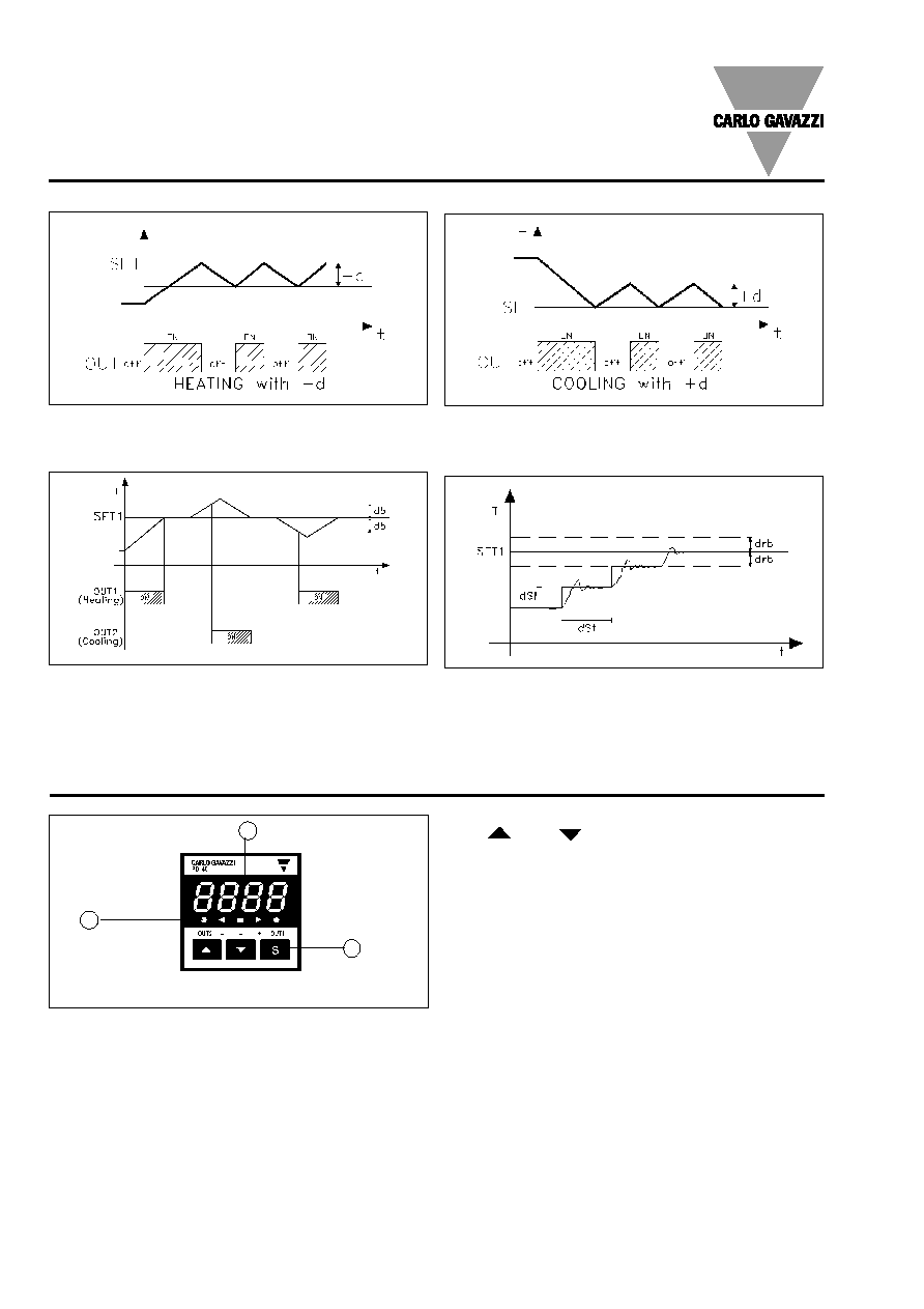
PDI 40
Front Panel Description
1
" " and " "
- Up and down keys for selecting programming parameters.
- S + Up and down Keys for value programming.
2. Display
4-digit (maximum read-out 7000).
Alphanumeric indication by means of 7-segment display for:
- Displaying of the measured value, over-range, burn-out
and programming indications.
- Indication of programming parameters.
3. LED's
4 red LEDs for the indication of:
- process variable under (≠) the setpoint limit
- process variable over (+) the setpoint limit
- activation of the first output (out 1)
- activation of the second output (out 2)
1 green LED for the indication of the process variable equal
to the setpoint.
1. Key-pad
Set-up and programming procedures are easily controlled
by the 3 pushbuttons.
"S"
- Key to enter the programming procedure
(instrument configuration)
2
3
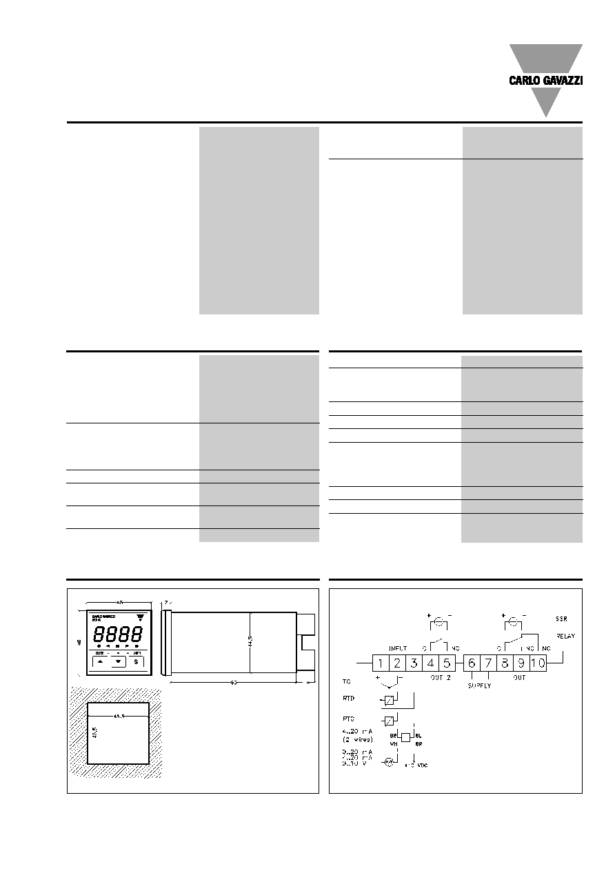
Output Controls
ON/OFF control
ON/OFF control
Fig. 1
Fig. 2
Neutral zone control
Fig. 3
Dynamic setpoint
Fig. 4
-d
= negative hysteresis
+ d = positive hysteresis
dB = dead band
drb = half band parameter
dSI = step increase
dSt = time interval between two step increases