
Specifications are subject to change without notice (30.09.2005)
1
Product Description
Ordering Key
Solid State Relays
System Monitoring Relays (Sense Relay)
Type RA.... .....S
∑ System (line and load) monitoring relay
∑ Zero switching
∑ Rated operational current: 25, 50, 90 and 110 AACrms
∑ Rated operational voltage: 120, 230, 400 and 480 VACrms
∑ High surge current capability
∑ Alarm output signal
∑ LED indication for alarm and supply
The system monitoring solid
state relay (sense relay) pro-
vides an alarm output in the
event of a circuit failure.
Internal circuits monitor:
- line voltage/line current
- correct functioning
of the SSR
- SSR input status
The relay is designed for
applications where immediate
fault detection is required.
A red LED indicates an
alarm, a green LED indicates
DC control supply OK (half
LED light intensity) resp.
relay switched ON (full LED
light intensity).
Solid State Relay
Switching mode
Rated operational voltage
Rated operational current
Control input
Non-rep. peak voltage
Alarm output type
Sense SSR
RA 23 25 H 06 NO S
Switching mode
Rated operational
Rated operational
Control
Non-rep. peak
Alarm output
voltage
current
input
voltage
type
A: Zero switching
12: 120 VACrms
25: 25 AACrms
H: Active high
06: 650 V
p
NO: NPN, NO
23: 230 VACrms
50: 50 AACrms
10: 1000 V
p
NC: NPN, NC
40: 400 VACrms
90: 90 AACrms
12: 1200 V
p
PO: PNP, NO
48: 480 VACrms
110: 110 AACrms
PC: PNP, NC
Rated
Control
Alarm
Rated operational current
op. input
output
voltage
type
25 AACrms
50 AACrms
90 AACrms
110 AACrms
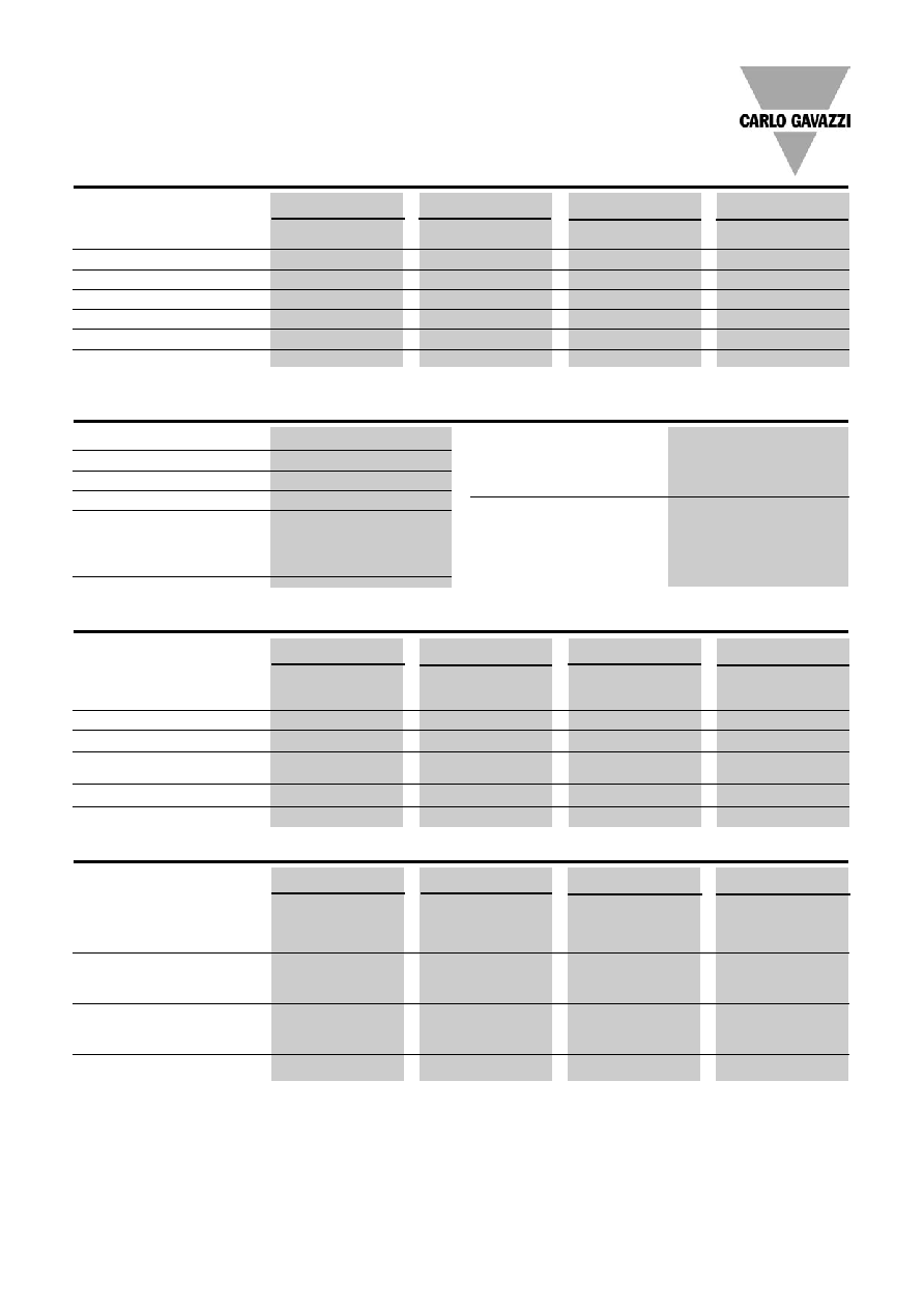
120
Active high
NPN, NO
RA 1225 H06NOS
RA 1250 H06NOS
RA 1290 H06NOS
RA 12110 H06NOS
VACrms
NPN, NC
RA 1225 H06NCS
RA 1250 H06NCS
RA 1290 H06NCS
RA 12110 H06NCS
PNP, NO
RA 1225 H06POS
RA 1250 H06POS
RA 1290 H06POS
RA 12110 H06POS
PNP, NC
RA 1225 H06PCS
RA 1250 H06PCS
RA 1290 H06PCS
RA 12110 H06PCS
230
Active high
NPN, NO
RA 2325 H06NOS
RA 2350 H06NOS
RA 2390 H06NOS
RA 23110 H06NOS
VACrms
NPN, NC
RA 2325 H06NCS
RA 2350 H06NCS
RA 2390 H06NCS
RA 23110 H06NCS
PNP, NO
RA 2325 H06POS
RA 2350 H06POS
RA 2390 H06POS
RA 23110 H06POS
PNP, NC
RA 2325 H06PCS
RA 2350 H06PCS
RA 2390 H06PCS
RA 23110 H06PCS
400
Active high
NPN, NO
RA 4025 H10NOS
RA 4050 H10NOS
RA 4090 H10NOS
RA 40110 H10NOS
VACrms
NPN, NC
RA 4025 H10NCS
RA 4050 H10NCS
RA 4090 H10NCS
RA 40110 H10NCS
PNP, NO
RA 4025 H10POS
RA 4050 H10POS
RA 4090 H10POS
RA 40110 H10POS
PNP, NC
RA 4025 H10PCS
RA 4050 H10PCS
RA 4090 H10PCS
RA 40110 H10PCS
480
Active high
NPN, NO
RA 4825 H12NOS
RA 4850 H12NOS
RA 4890 H12NOS
RA 48110 H12NOS
VACrms
NPN, NC
RA 4825 H12NCS
RA 4850 H12NCS
RA 4890 H12NCS
RA 48110 H12NCS
PNP, NO
RA 4825 H12POS
RA 4850 H12POS
RA 4890 H12POS
RA 48110 H12POS
PNP, NC
RA 4825 H12PCS
RA 4850 H12PCS
RA 4890 H12PCS
RA 48110 H12PCS
Type Selection
Selection Guide
2
Specifications are subject to change without notice (30.09.2005)
Supply voltage range
20 to 32 VDC
Supply current @ 24 VDC
40 mA DC
Response time pick-up @ 50 Hz
10 ms
Response time drop-out @ 50 Hz
10 ms
Active high control input
Pick-up voltage
Typ. 7 VDC
Drop-out voltage
Typ. 6.8 VDC
Input current (Vc = 32 V)
4 mA
RA.... .....S
PNP Alarm output
Alarm output voltage open
0 VDC
Alarm output voltage @ 100 mA
Vcc - 2 VDC
Alarm output current
100 mA
NPN Alarm output
Alarm output voltage open
32 VDC
Alarm output voltage @ 100 mA
2 VDC
Alarm output current
100 mA
General Specifications
Control Specifications
Output Specifications
Sense Specifications
RA12...06..S
RA23...06..S
RA40...10..S
RA48...12..S
Operational voltage range
60 to 140 VACrms
170 to 250 VACrms
150 to 440 VACrms
180 to 530 VAC
Non-rep. peak voltage
650 V
p
650 V
p
1000 V
p
1200 V
p
Zero voltage turn-on
15 V
15 V
15 V
25 V
Operational frequency range
45 to 65 Hz
45 to 65 Hz
45 to 65 Hz
45 to 65 Hz
Power factor cos
0.5 @ 120 VACrms
0.5 @ 230 VACrms
0.5 @ 400 VACrms
0.5 @ 480 VACrms
Approvals
UL, CSA
UL, CSA
UL, CSA
UL, CSA
CE-marking
Yes
Yes
Yes
Yes
RA..25.06..S
RA..50.06..S
RA..90.10..S
RA..110.12..S
Rated operational current AC 51
25 Arms
50 Arms
90 Arms
110 Arms
AC 53a 5 Arms
15 Arms
20 Arms
30 Arms
Min. operational load current
200 mA
200 mA
200 mA
200 mA
Non-rep. surge current t=10 ms
300 A
p
580 A
p
1150 A
p
1900 A
p
Off-state leakage current
@ rated voltage and frequency
6 mA
6 mA
6 mA
6 mA
I
2
t for fusing t=1-10 ms
450 A
2
s
1680 A
2
s
6600 A
2
s
18000 A
2
s
Critical dv/dt
500 V/µs
500 V/µs
500 V/µs
500 V/µs
RA12..06..S
RA23..06..S
RA40..10..S
RA48..12..S
Current
Sensed load current
50 mA
50 mA
50 mA
50 mA
Non-sensed leakage current
20 mA
20 mA
20 mA
20 mA
Voltage
Sensed line voltage
60 Vrms
120 Vrms
150 Vrms
180 Vrms
Non-sensed line voltage
30 Vrms
50 Vrms
80 Vrms
100 Vrms
Timing
Response time from fault to
alarm output
100 ms
100 ms
100 ms
100 ms
Short-circuit of semiconductor
Will be sensed
Will be sensed
Will be sensed
Will be sensed
Specifications are subject to change without notice (30.09.2005)
3
RA.... .....S
RA..25.....S
RA..50.....S
RA..90.....S
RA..110.....S
Operating temperature
-20∞ to +70∞C
-20∞ to +70∞C
-20∞ to +70∞C
-20∞ to +70∞C
(-4∞ to +158∞F)
(-4∞ to +158∞F)
(-4∞ to +158∞F)
(-4∞ to +158∞F)
Storage temperature
-40∞ to +100∞C
-40∞ to +100∞C
-40∞ to +100∞C
-40∞ to +100∞C
(-40∞ to +212∞C)
(-40∞ to +212∞C)
(-40∞ to +212∞C)
(-40∞ to +212∞C)
Junction temperature
125∞C (257∫F)
125∞C (257∫F)
125∞C (257∫F)
125∞C (257∫F)
R
th
junction to case
1.25 K/W
0.65 K/W
0.35 K/W
0.30 K/W
R
th
junction to ambient
12 K/W
12 K/W
12 K/W
12 K/W
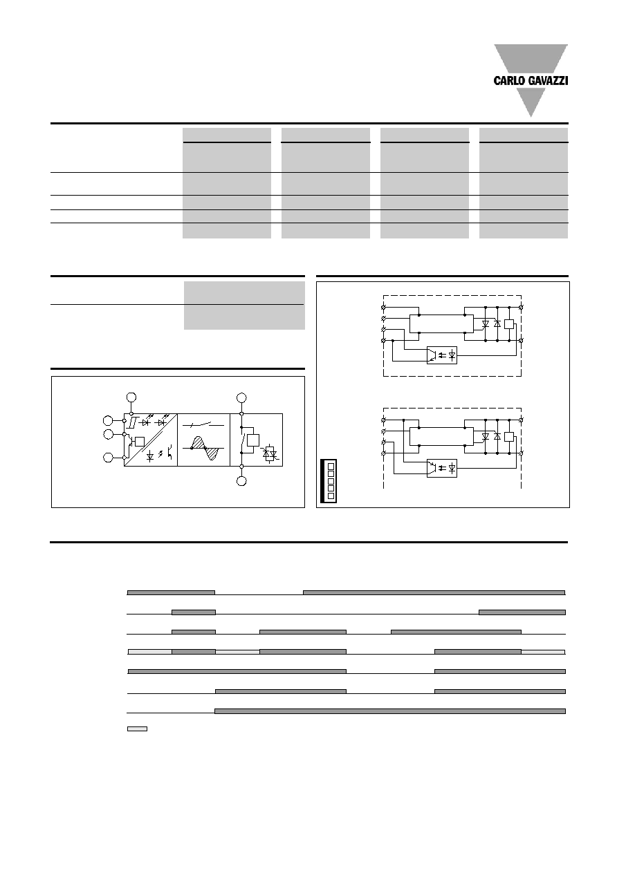
Mains input/load output
Load output/mains input
1
2
3
7
4
6
C/V
VCC
Control
input
Com.
Alarm
output
Rated insulation voltage
Input to output
4000 VACrms
Rated insulation voltage
Output to case
4000 VACrms
C/V
IC
Alarm output
Control input
+ 3
6
7
4
2
1
Line/load
RAxxxxxxNxS
1
+ 3
6
7
4
IC
Alarm output
Control input
2
Line/load
RAxxxxxxPxS
4 -
5 Not con.
3 +
6 Control
7 Alarm
Thermal Specifications
Insulation
Wiring Diagrams
Functional Diagram
Normal Operation
Relay Relay
OFF
ON
Line
Voltage
Loss
Line
Voltage
Loss
Load
Open
Circuit
DC
Supply
Loss
DC
Supply
Loss
Relay
Remains
OFF
Shorted
Relay
Shorted
Relay
Line Voltage
= Half LED light intensity
Operation Diagram
Load Current
Control
Green LED
DC Supply
Red LED
Alarm output (normally open type)
4
Specifications are subject to change without notice (30.09.2005)
0.92
0.76
0.60
0.45
0.29
- 63
1.2
0.99
0.80
0.62
0.44
0.26
55
1.5
1.3
1.1
0.85
0.63
0.42
47
1.9
1.6
1.4
1.1
0.89
0.63
40
2.4
2.1
1.8
1.5
1.2
0.91
33
3
2.7
2.3
1.9
1.5
1.1
26
3.9
3.5
3
2.5
2
1.5
20
5.5
4.8
4.1
3.4
2.7
2.1
15
8.6
7.5
6.4
5.4
4.3
3.2
9
17.9
15.6
13.4
11.2
8,9
6.7
4
20
30
40
50
60
70
50
45
40
35
30
25
20
15
10
5
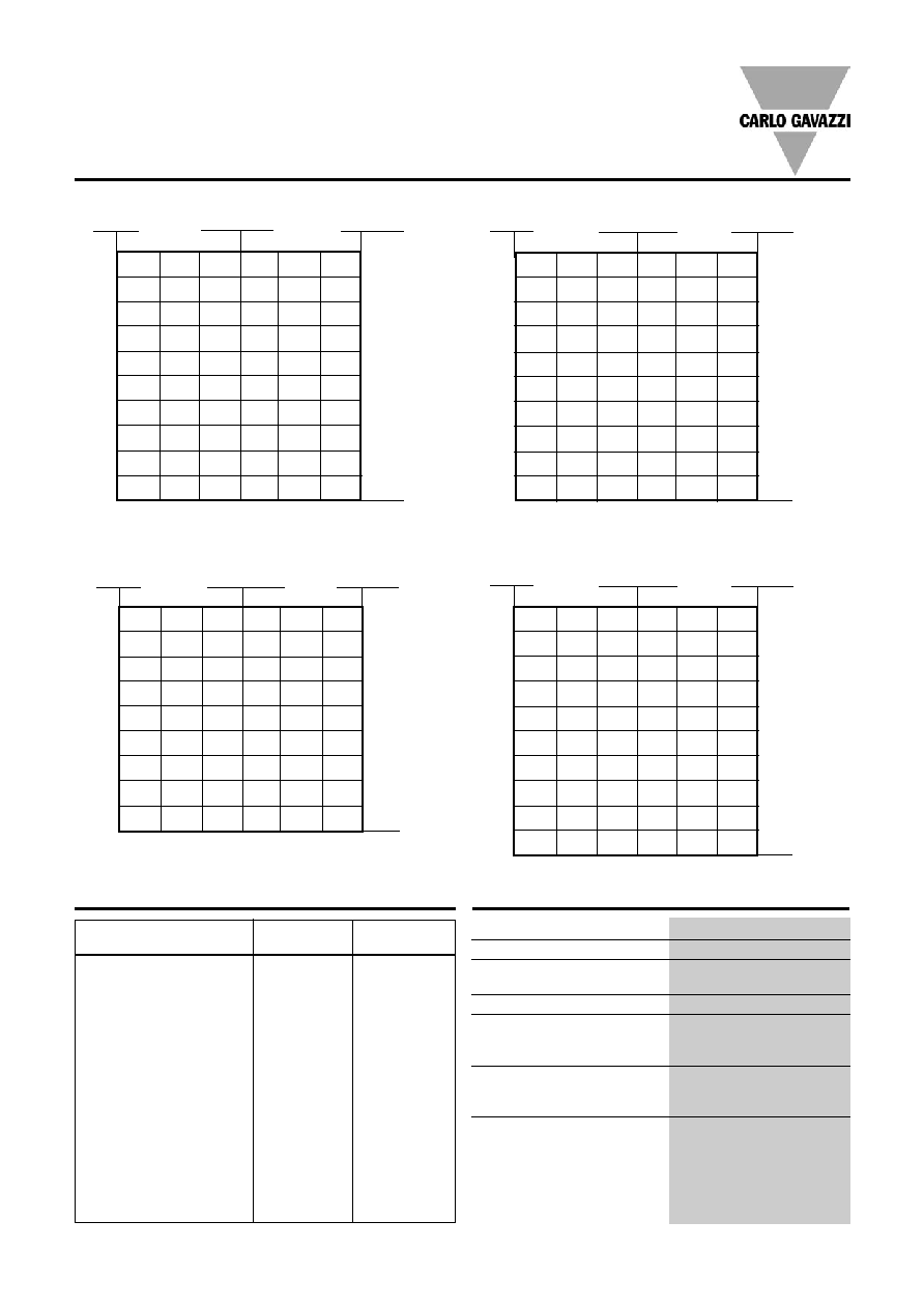
RA ..90 .....S
RA ..25 .....S
RA ..50 .....S
T
A
Ambient temp. [
∞
C]
Power dissipa-
tion [W]
Thermal resistance
[K/W]
Load
current [A]
Power dissipa-
tion [W]
2
1.7
1.4
1
0.71
0.40 32
2.5
2.1
1.8
1.4
1
0.66
27
3.1
2.7
2.3
1.9
1.4
1
23
4
3.5
3
2.5
2
1.4
20
4.9
4.3
3.7
3.1
2.5
1.9
16
6.2
5.4
4.6
3.9
3.1
2.3
13
8.1
7.1
6.1
5.1
4
3
10
11.3
9.9
8.5
7.1
5.6
4.2
7
-
15.6
13.3
11.1
8.9
6.7
5
-
-
-
-
18.7
14
2
20
30
40
50
60
70
25
22.5
20
17.5
15
12.5
10
7.5
5
2.5
T
A
Ambient temp. [
∞
C]
Load
current [A]
Thermal resistance
[K/W]
90
80
70
60
50
40
30
20
10
0.63
0.53
0.42
0.32
-
-
97
0.81
0.69
0.57
0.45
0.33
-
84
1
0.89
0.75
0.61
0.47
0.33
71
1.3
1.2
1
0.83
0.66
0.49
59
1.7
1.5
1.3
1.1
0.85
0.64
47
2.2
1.9
1.7
1.4
1.1
0.83
36
3.1
2.7
2.3
1.9
1.5
1.2
26
4.8
4.2
3.6
3
2.4
1.8
17
10
8.8
7.5
6.3
5
3.8
8
20
30
40
50
60
70
T
A
Ambient temp. [
∞
C]
Thermal resistance
[K/W]
Load
current [A]
Power dissipa-
tion [W]
RA.... .....S
Heatsink Dimensions
(load current versus ambient temperature)
Housing Specifications
Weight
Approx. 110 g
Housing material
Noryl GFN 1, black
Base plate 25, 50 A
Aluminium, nickel-plated
90, 110 A
Coper, nickel-plated
Potting compound
Polyurethane
Relay
Mounting screws
M5
Mounting torque
1.5 Nm
Power terminal
Mounting screws
M5 x 6
Mounting torque
2.4 Nm
Control connector
5 pole,
centre distance 2.54 mm
RA ..110 .....S
T
A
Ambient temp. [
∞
C]
0.43
0.35
0.27
-
-
- 126
0.63
0.53
0.42
0.32
-
-
97
0.81
0.69
0.57
0.45
0.33
-
84
1
0.89
0.75
0.61
0.47
0.33
71
1.3
1.2
1
0.83
0.66
0.49
59
1.7
1.5
1.3
1.1
0.85
0.64
47
2.2
1.9
1.7
1.4
1.1
0.83
36
3.1
2.7
2.3
1.9
1.5
1.2
26
4.8
4.2
3.6
3
2.4
1.8
17
10
8.8
7.5
6.3
5
3.8
8
20
30
40
50
60
70
110
90
80
70
60
50
40
30
20
10
Power dissipa-
tion [W]
Thermal resistance
[K/W]
Load
current [A]
Carlo Gavazzi Heatsink Thermal
...for
power
(See "General Accessories")
resistance..
dissipation
No heatsink required
---
N/A
RHS 300
5.00 K/W
> 0 W
RHS 100
3.00 K/W
> 25 W
RHS 45C
2.70 K/W
> 60 W
RHS 45B
2.00 K/W
> 60 W
RHS 90A
1.35 K/W
> 60 W
RHS 45A plus fan
1.25 K/W
> 0 W
RHS 45B plus fan
1.20 K/W
> 0 W
RHS 112A
1.10 K/W
> 100 W
RHS 301
0.80 K/W
> 70 W
RHS 90A plus fan
0.45 K/W
> 0 W
RHS 112A plus fan
0.40 K/W
> 0 W
RHS 301 plus fan
0.25 K/W
> 0 W
Consult your distributor
> 0.25 K/W
N/A
Infinite heatsink - No solution
---
N/A
Heatsink Selection

Specifications are subject to change without notice (30.09.2005)
5
RA.... .....S
R-System
Cable sense
5-wire
Cable length in cm
*
0: No connector mounted (Method 1300-105-424)
1: 1 connector mounted
2: 2 connectors mounted
Heatsinks
DIN rail adapter
Varistors
Fuses
Connector for ribbon cable:
Methode 1300-105-424
Header for PCB mounting:
Methode 1100-8-105-01
Ribbon cable:
5 x 0.5 mm
2
,
centre distance 2.54 mm
All dimensions in mm
Dimensions
Accessories
Ribbon Cable Selection
RCS 5-200-0*