Specifications are subject to change without notice (14.07.2003)
1
∑
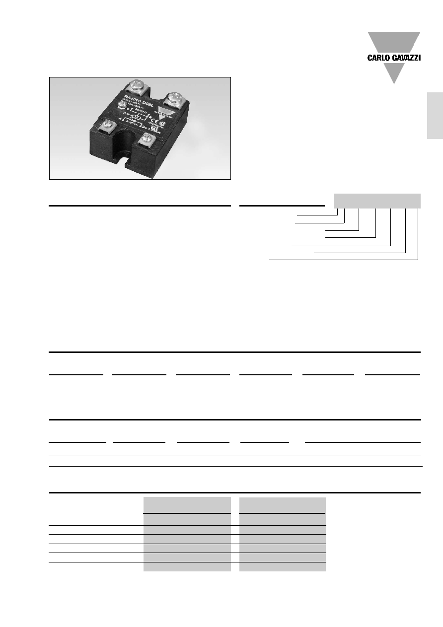
AC Solid State Relay
∑
Zero switching
∑
For ohmic load applications
∑
Rated operational current: 10 and 25 AACrms
∑
Rated operational voltage: Up to 400 VACrms
∑
10 A type meets CISPR 22 B requirements
This relay is designed for use
in applications where low
electromagnetic emission is
essential.
Today, household and electri-
cal appliances, information
technology- and medical
equipment must conform with
the latest EN standards.
These new EN standards de-
fine general and product relat-
ed requirements for noise im-
munity and noise emission.
The RA24..-D06L and RA40..-
D08L are relays for applica-
Ordering Key
Solid State Relays
Solid State Relay
Switching mode
Rated operational voltage
Rated operational current
Control voltage
Non-rep. peak voltage
Low RFI
tions where the noise emis-
sion must be low and where
the customer does not want
to relinquish all Solid State Re-
lay features. The relay is avail-
able with zero crossing func-
tion. It is designed for resistive
loads, i.e. power factor = 1.
Predestined applications for
this relay are office machines,
ovens and cookers for domes-
tic and industrial use, theatre
or stage lighting systems, film
processing and copying ma-
chines or medical equipment.
Product Description
RA 24.. -D 06 L
RA 40.. -D 08 L
Operational voltage range
180 to 265 VACrms
340 to 530 VACrms
Non-rep. peak voltage
650 V
p
850 V
p
Operational frequency range
45 to 65 Hz
45 to 65 Hz
Power factor
1
1
Approvals
UL, cUL, CSA, VDE
UL, cUL, CSA, VDE
CE-marking
Yes
Yes
Type Selection
Switching mode
Rated opera-
Rated operational
Control voltage
Non-rep. voltage
Electromagnetic
tional voltage
current
noise emission
A: Zero switching
24: 230 VACrms
10: 10 AACrms
-D: 3 to 32 VDC
06: 650 V
p
L: Low RFI
40: 400 VACrms
25: 25 AACrms
08: 850 V
p
Selection Guide
General Specifications
Rated operational Non-rep. voltage
Electromagnetic
Control voltage
Rated operational current
voltage
noise emission
10 AACrms
25 AACrms
230 VACrms
650 V
p
Low RFI
3 to 32 VDC
RA 2410 -D 06 L
RA 2425 -D 06 L
400 VACrms
850 V
p
Low RFI
3 to 32 VDC
RA 4010 -D 08 L
RA 4025 -D 08 L
Low Electromagnetic Noise Emission
Types RA 24.. -D 06 L, RA 40.. -D 08 L
RA 24 25 -D 06 L
2
Specifications are subject to change without notice (14.07.2003)
RA 24.. -D 06 L, RA 40.. -D 08 L
Control voltage range
3 to 32 VDC
Pick-up voltage
3 V
Drop-out voltage
1 V
Reverse voltage
32 VDC
Input impedance
1 k
Response time
1/2 cycle
Input Specifications
Insulation
Rated insulation voltage
Input to output
4000 VACrms
Rated insulation voltage
Output to case
4000 VACrms
Reference voltage
500 VACrms
Insulation meets VDE 0700
requirements
Output Specifications
RA ..10 -D 0. L
RA ..25 -D 0. L
Rated operational current AC 51 10 Arms
25 Arms
Min. operational current AC 51
1 Arms
2 Arms
Rep. overload current t=1 s
30 A
p
50 A
p
Non-rep. surge current t=20 ms 90 A
p
200 A
p
Off-state leakage current
1 mArms
1 mArms
I
2
t for fusing t=1-10 ms
120 A
2
s
200 A
2
s
On-state voltage drop
1.2 Vrms
1.2 Vrms
Critical dV/dt off-state
250 V/
µ
s
250 V/
µ
s
Synchronization current
20 mArms
20 mArms
Thermal Specifications
RA ..10 -D 0. L
RA ..25 -D 0. L
Operating temperature range
-20∞ to +70∞C (-4∞ to +158∞F)
-20∞ to +70∞C (-4∞ to +158∞F)
Storage temperature range
-40∞ to +100∞C (-40∞ to +212∞F)
-40∞ to +100∞C (-40∞ to +212∞F)
Junction temperature
125∞C (257∞F)
125∞C (257∞F)
R
th
junction to case
2.5 K/W
1.8 K/W
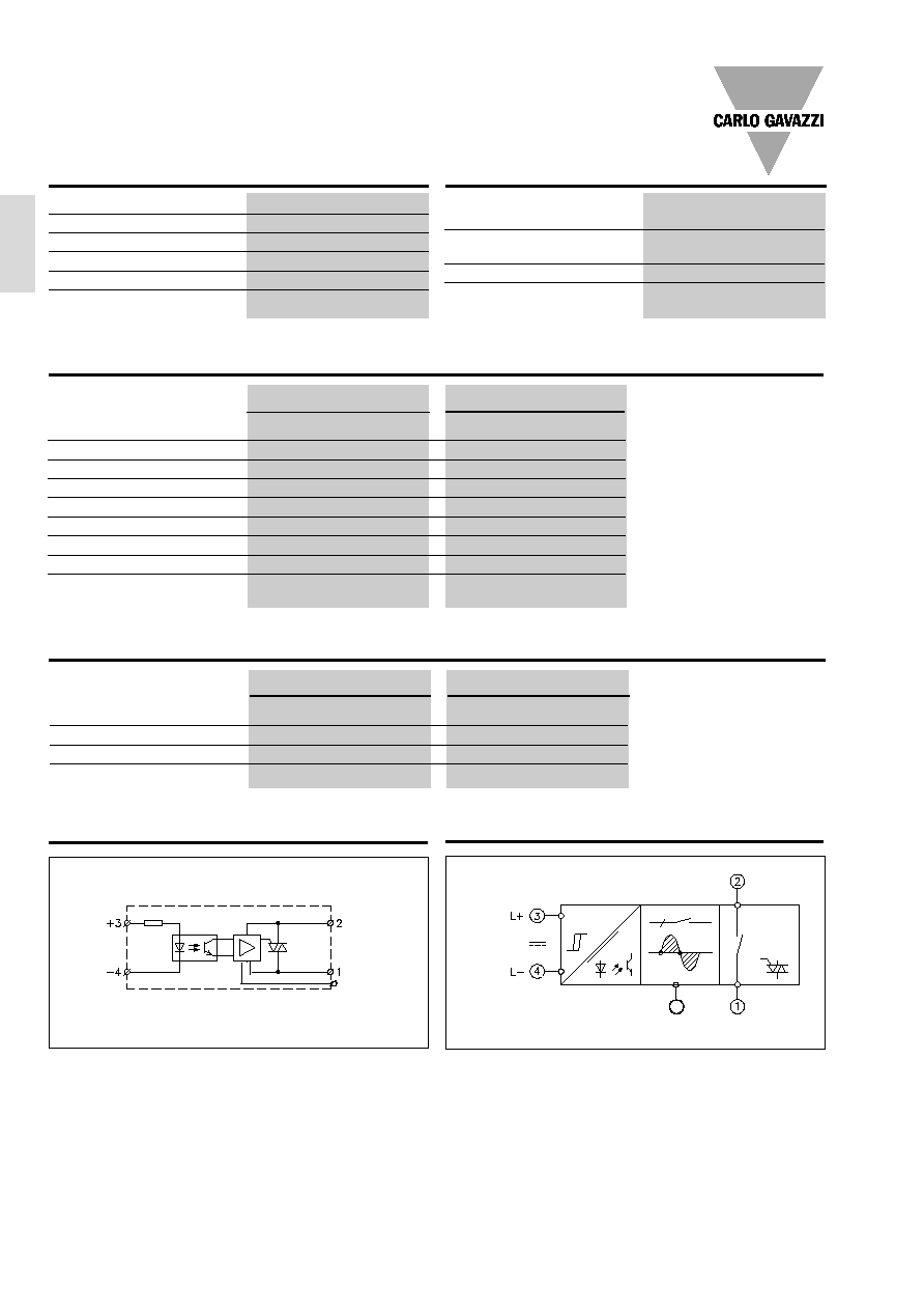
Control
input
Functional Diagram
Wiring Diagram
Control
input
Line
Load
S Synchr.
voltage
Mains input
Load output
Synchr.
voltage
S
Specifications are subject to change without notice (14.07.2003)
3
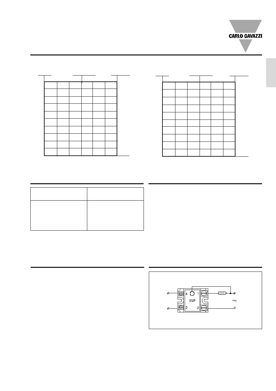
Heatsink Dimensions
(load current versus ambient temperature)
RA 24.. -D 06 L, RA 40.. -D 08 L
RA ..10 -D 0. L
5.7
5.0
4.3
3.6
2.8
2.0
14
6.2
5.4
4.6
3.9
3.1
2.2
12
7.4
6.4
5.5
4.6
3.7
2.7
11
8.5
7.4
6.3
5.3
4.2
3.1
9
9.8
8.6
7.4
6.1
4.9
4.9
8
-
10.2
8.7
7.2
5.8
6.2
7
-
-
10.5
8.7
7.0
5.7
6
-
-
-
10.7
8.5
4.7
5
-
-
-
-
10.8
8.1
4
-
-
-
-
-
10.7
3
20
30
40
50
60
70
10
9
8
7
6
5
4
3
2
1
T
A
Thermal resistance
[K/W]
Power
dissipation [W]
Load
current [A]
RA ..25 -D 0. L
1.0
0.8
0.5
0.25
-
-
38
1.5
1.1
0.8
0.5
0.26
-
33
1.9
1.6
1.2
0.9
0.5
-
29
2.5
2.1
1.7
1.3
0.9
0.5
25
3.3
2.9
2.4
1.9
1.4
1.0
21
4.4
3.9
3.3
2.7
2.1
1.5
17
5.7
5.0
4.3
3.6
2.9
2.1
14
7.5
6.6
5.6
4.7
3.7
2.8
11
10.6
9.3
8.0
6.6
5.3
4.0
8
-
-
-
10.7
8.5
6.4
5
20
30
40
50
60
70
T
A
Ambient temp. [
∞
C]
Load
current [A]
Thermal resistance
[K/W]
Power
dissipation [W]
Ambient temp. [
∞
C]
25
22.5
20
17.5
15
12.5
10
7.5
5
2.5
Carlo Gavazzi Heatsink
(see Accessories)
No heatsink required
RHS 100 Assy
RHS 301 Assy
RHS 301 F Assy
Consult your distributor
Heatsink Selection
Thermal resistance
R
th s-a
> 12.5
K/W
3.0 K/W
0.8 K/W
0.25 K/W
< 0.25 K/W
The very low, wire-conduct-
ed RFI feature of this relay is
obtained by synchronized fir-
ing of the output triac in the
zero crossing of the mains
voltage. Therefore the relay
must have the synchroniza-
tion input connected to the
mains, either to neutral or to
the phase depending on how
the load is connected.
The relay can only switch re-
sistive loads with a power fac-
tor of 1.
A minimal load current of 1A
for the RA ..10 -D 0. L and 2 A
for the RA ..25 -D 0. L is re-
quired as long as the control
input is activated.
Applications
Compare the value found in the current versus temperature
chart with the standard heatsink values and select the heat-
sink with the next lower value.
Accessories
Heatsinks
DIN rail adapter
Varistors
Fuses
Connection Diagram
Control
input
N/L
2
L
1
S
Load
For further information refer
to "General Accessories".

4
Specifications are subject to change without notice (14.07.2003)
RA 24.. -D 06 L, RA 40.. -D 08 L
Weight
Approx. 110 g
Housing material
Noryl GFN 1, black
Base plate
Aluminium
Potting compound
Polyurethane
Relay
Mounting screws
M5
Mounting torque
1.5 Nm
Control and Synchr. terminal
Mounting screws
M3 x 6
Mounting torque
0.5 Nm
Power terminal
Mounting screws
M5 x 6
Mounting torque
2.4 Nm
Dimensions
** =
±
0.4 mm
***=
±
0.5 mm
**
**
***
***
***
***
Housing Specifications
Connection Examples
RA24xx-D06L and RA40xx-D08L
3-phase application with three heat elements.
SSR
SSR
L1
L2
L3
SSR
L1
L2
2-phase application with one heat element.
SSR
SSR
L1
L2
N
SSR
L2
SSR
L1
N
1-phase application without ground.
3-phase application with two heat elements without ground.