
2-60
Specifications are subject to change without notice (30.09.2005)
∑
AC Solid State Relay
∑
Zero switching
∑
Direct copper bonding technology
∑
Rated operational current: 10, 25, 50 and 90 AACrms
∑
Non-repetitive voltage: Up to 1200 V
p
∑
Rated operational voltage: Up to 480 VACrms
∑
3 input ranges: 3 to 32 VDC, 10 to 90 VAC/DC and
90 to 280 VAC/DC
∑
Insulation: OPTO (input-output) 4000 VACrms
Product Description
The zero switching relay with
antiparallel thyristor output is
the most widely used indus-
trial SSR due to its multiple
application possibilities. The
relay can be used for resis-
Solid State Relay
Switching mode
Rated operational voltage
Rated operational current
Control voltage
Non-rep. peak voltage
Ordering Key
Solid State Relays
tive, inductive and capacitive
loads. The zero switching re-
lay switches ON when the
sine curve just crosses zero
and switches OFF when the
current crosses zero.
Type Selection
Switching mode
Rated operational
Rated operational
Control voltage
Non-rep. voltage
voltage
current
A: Zero switching
24: 230 VACrms
10: 10 AACrms
-D: 3 to 32 VDC
06: 650 V
p
44: 400 VACrms
25: 25 AACrms
LA: 10 to 90 VAC/DC
08: 850 V
p
48: 480 VACrms
50: 50 AACrms
HA: 90 to 280 VAC/DC
12: 1200 V
p
90: 90 AACrms
Selection Guide
Rated opera-
Non-rep. Control voltage
Rated operational current
tional voltage voltage
10 AACrms
25 AACrms
50 AACrms
90 AACrms
3 to 32 VDC
RA 2410 -D 06
RA 2425 -D 06
RA 2450 -D 06
RA 2490 -D 06
230 VACrms
650 V
p
10 to 90 VAC/DC
RA 2410 LA 06
RA 2425 LA 06
RA 2450 LA 06
RA 2490 LA 06
90 to 280 VAC/DC
RA 2410 HA 06
RA 2425 HA 06
RA 2450 HA 06
RA 2490 HA 06
3 to 32 VDC
RA 4410 -D 08
RA 4425 -D 08
RA 4450 -D 08
RA 4490 -D 08
400 VACrms
850 V
p
10 to 90 VAC/DC
RA 4410 LA 08
RA 4425 LA 08
RA 4450 LA 08
RA 4490 LA 08
90 to 280 VAC/DC
RA 4410 HA 08
RA 4425 HA 08
RA 4450 HA 08
RA 4490 HA 08
3 to 32 VDC
RA 4810 -D 12
RA 4825 -D 12
RA 4850 -D 12
RA 4890 -D 12
480 VACrms
1200 V
p
10 to 90 VAC/DC
RA 4810 LA 12
RA 4825 LA 12
RA 4850 LA 12
RA 4890 LA 12
90 to 280 VAC/DC
RA 4810 HA 12
RA 4825 HA 12
RA 4850 HA 12
RA 4890 HA 12
Industrial, 1-Phase ZS, Standard Range
Types RA 24.. .. 06/RA 44.. .. 08/RA 48.. .. 12
RA 24 10 LA 06
Specifications are subject to change without notice (30.09.2005)
2-61
RA 24.. .. 06, RA 44.. .. 08, RA 48.. .. 12
RA 24.. .. 06
RA 44.. .. 08
RA 48.. .. 12
Operational voltage range
24 to 280 VACrms
42 to 480 VACrms
42 to 530 VACrms
Non-rep. peak voltage
650 V
p
850 V
p
1200 V
p
Zero voltage turn-on
20 V
40 V
40 V
Operational frequency range
45 to 65 Hz
45 to 65 Hz
45 to 65 Hz
Power factor
0.5 @ 230 VACrms
0.5 @ 400 VACrms
0.5 @ 480 VACrms
Approvals
UL, CSA
UL, CSA
UL, CSA
General Specifications
RA .... -D ..
RA .... LA ..
RA .... HA ..
Control voltage range
3 to 32 VDC
10 to 90 VAC/DC
90 to 280 VAC/DC
Pick-up voltage
3 VDC
10 VAC/DC
90 VAC/DC
Drop-out voltage
1 VDC
1 VAC/DC
10 VAC/DC
Reverse voltage
32 VDC
Input impedance
1.5 k
5.4 k
44 k
Response time pick-up
1/2 cycle
1 cycle
1 cycle
Control pulse width
0.5 ms
0.5 ms
0.5 ms
Response time drop-out
1/2 cycle
1/2 cycle
1/2 cycle
Input Specifications
Output Specifications
RA ..10 .. ..
RA ..25 .. ..
RA ..50 .. ..
RA ..90 .. ..
Rated operational current AC 51
16 Arms
25 Arms
50 Arms
90 Arms
AC 53a 3 Arms
5 Arms
15 Arms
20 Arms
Minimum operational current
20 mArms
20 mArms
20 mArms
20 mArms
Rep. overload current t=1 s
35 Arms
55 Arms
125 Arms
150 Arms
Non-rep. surge current t=10 ms 160 A
p
300 A
p
580 A
p
1150 A
p
Off-state leakage current
@ rated voltage and frequency
2.5 mArms
3 mArms
3 mArms
3 mArms
I
2
t for fusing t=1-10 ms
130 A
2
s
450 A
2
s
1680 A
2
s
6600 A
2
s
Critical dI/dt
50 A/µs
50 A/µs
50 A/µs
100 A/µs
On-state voltage drop
@ rated current
1.6 Vrms
1.6 Vrms
1.6 Vrms
1.6 Vrms
Critical dV/dt commutating
500 V/µs
500 V/µs
500 V/µs
500 V/µs
Critical dV/dt off-state
500 V/µs
500 V/µs
500 V/µs
500 V/µs
RA ..10 .. ..
RA ..25 .. ..
RA ..50 .. ..
RA ..90 .. ..
Operating temperature
-20
∞
to +70
∞
C
-20
∞
to +70
∞
C
-20
∞
to +70
∞
C
-20
∞
to +70
∞
C
(-4∞ to +158∞F)
(-4∞ to +158∞F)
(-4∞ to +158∞F)
(-4∞ to +158∞F)
Storage temperature
-40
∞
to +100
∞
C
-40
∞
to +100
∞
C
-40
∞
to +100
∞
C
-40
∞
to +100
∞
C
(-40∞ to +212∞F)
(-40∞ to +212∞F)
(-40∞ to +212∞F)
(-40∞ to +212∞F)
Junction temperature
125
∞
C (
257∞F)
125
∞
C (
257∞F)
125
∞
C (
257∞F)
125
∞
C (
257∞F)
R
th
junction to case
2.0 K/W
1.25 K/W
0.65 K/W
0.3 K/W
R
th
junction to ambient
12.5 K/W
12 K/W
12 K/W
12 K/W
Thermal Specifications
2-62
Specifications are subject to change without notice (30.09.2005)
RA 24.. .. 06, RA 44.. .. 08, RA 48.. .. 12
Rated insulation voltage
Input to output
4000 VACrms
Rated insulation voltage
Output to case
4000 VACrms
Insulation resistance
Input to output
10
10
Insulation resistance
Ouput to case
10
10
Insulation capacitance
Input to output
8 pF
Insulation capacitance
Output to case
100 pF
Insulation
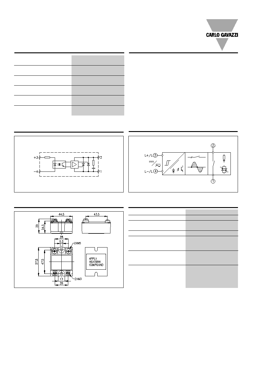
Wiring Diagram
Functional Diagram
Control
input
Mains input/load output
Control
input
Line/load
All dimensions in mm
Dimensions
Load output/mains input
Weight
Approx. 110 g
Housing material
Noryl GFN 1, black
Base plate 10, 25, 50 A
Aluminium, nickel-plated
90 A
Copper, nickel-plated
Potting compound
Polyurethane
Relay
Mounting screws
M5
Mounting torque
1.5 Nm
Control terminal
Mounting screws
M3 x 6
Mounting torque
0.5 Nm
Power terminal
Mounting screws
M5 x 6
Mounting torque
2.4 Nm
Housing Specifications
** =
±
0.4 mm
*** =
±
0.5 mm
**
**
***
***
***
***
Accessories
Protection cover
Heatsinks
DIN rail adapter
Varistors
Fuses
For further information refer
to "General Accessories".
Specifications are subject to change without notice (30.09.2005)
2-63
RA 24.. .. 06, RA 44.. .. 08, RA 48.. .. 12
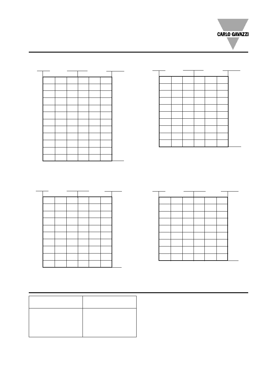
Heatsink Dimensions
(load current versus ambient temperature)
16
15
14
13
12
11
10
9
7
5
3
1
Load
current [A]
Thermal resistance
[K/W]
T
A
Ambient temp. [
∞
C]
Power
dissipation [W]
Power
dissipation [W]
2
1.7
1.4
1
0.71
0.40 32
2.5
2.1
1.8
1.4
1
0.66
27
3.1
2.7
2.3
1.9
1.4
1
23
4.
3.5
3
2.5
2
1.4
20
4.9
4.3
3.7
3.1
2.5
1.9
16
6.2
5.4
4.6
3.9
3.1
2.3
13
8.1
7.1
6.1
5.1
4
3
10
11.3
9.9
8.5
7.1
5.6
4.2
7
-
15.6
13.3
11.1
8.9
6.7
5
-
-
-
-
18.7
14
2
20
30
40
50
60
70
25
22.5
20
17.5
15
12.5
10
7.5
5
2.5
T
A
Ambient temp. [
∞
C]
Load
current [A]
RA ..50 .. ..
T
A
Ambient temp. [
∞
C]
50
45
40
35
30
25
20
15
10
5
Power
dissipation [W]
Thermal resistance
[K/W]
Load
current [A]
Thermal resistance
[K/W]
2.7
2.2
1.8
1.3
0.87
0.41
22
3.1
2.6
2.1
1.7
1.2
0.65
20
3.7
3,1
2.6
2
1.5
0.92
18
4.3
3.7
3.1
2.5
1.9
1.2
16
5
4.3
3.7
3
2.3
1.6
15
5.9
5.1
4.4
3.6
2.8
2.1
13
6.9
6
5.2
4.3
3.5
2.6
12
7.9
6.9
5.9
4.9
4
3
10
10.8
9.5
8.1
6.8
5.4
4.1
7
-
14.2
12.2
10.2
8.1
6.1
5
-
-
-
-
14.6
10.9
3
-
-
-
-
-
-
1
20
30
40
50
60
70
0.92
0.76
0.60
0.45
0.29
- 63
1.2
0.99
0.80
0.62
0.44
0.26
55
1.5
1.3
1.1
0.85
0.63
0.42
47
1.9
1.6
1.4
1.1
0.89
0.63
40
2.4
2.1
1.8
1.5
1.2
0.91
33
3
2.7
2.3
1.9
1.5
1.1
26
3.9
3.5
3
2.5
2
1.5
20
5.5
4.8
4.1
3.4
2.7
2.1
15
8.6
7.5
6.4
5.4
4.3
3.2
9
17.9
15.6
13.4
11.2
8,9
6.7
4
20
30
40
50
60
70
Thermal resistance
[K/W]
Load
current [A]
Power
dissipation [W]
RA ..90 .. ..
T
A
Ambient temp. [
∞
C]
0.63
0.53
0.42
0.32
-
-
97
0.81
0.69
0.57
0.45
0.33
-
84
1
0.89
0.75
0.61
0.47
0.33
71
1.3
1.2
1
0.83
0.66
0.49
59
1.7
1.5
1.3
1.1
0.85
0.64
47
2.2
1.9
1.7
1.4
1.1
0.83
36
3.1
2.7
2.3
1.9
1.5
1.2
26
4.8
4.2
3.6
3
2.4
1.8
17
10
8.8
7.5
6.3
5
3.8
8
20
30
40
50
60
70
90
80
70
60
50
40
30
20
10
Carlo Gavazzi Heatsink
(see Accessories)
No heatsink required
RHS 100 Assy
RHS 301 Assy
RHS 301 F Assy
Consult your distributor
Heatsink Selection
Thermal resistance
R
th s-a
> 12.5
K/W
3.0 K/W
0.8 K/W
0.25 K/W
< 0.25 K/W
Compare the value found in the current versus temperature
chart with the standard heatsink values and select the heat-
sink with the next lower value.
RA ..10 .. ..
RA ..25 .. ..

2-64
Specifications are subject to change without notice (30.09.2005)
Applications
Thermal characteristics
The thermal design of Solid
State Relays is very impor-
tant. It is essential that the user
makes sure that cooling is ad-
equate and that the maximum
junction temperature of the re-
lay is not exceeded.
This relay is designed for use
in applications in which it is
exposed to high surge condi-
tions. Care must be taken to
ensure proper heatsinking
when the relay is to be used at
high sustained currents. Ade-
quate electrical connection
between relay terminals and
cable must be ensured.
RA 24.. .. 06, RA 44.. .. 08, RA 48.. .. 12
Heat flow
Heatsink
temperature
R
th
j-c
R
th
c-s
R
th
s-a
Junction
temperature
Case
temperature
Ambient
temperature
Thermal resistance:
R
th
j-c = junction to case
Direct bonding
In the design of the output
power semiconductor direct
bonding of the copper layer
and the ceramic substrate has
been applied. This is to en-
sure uninhibited heat transfer
and high thermal fatigue
strength.
The relay has been designed
for applications requiring lar-
ge numbers of load cycles.
Power dissipation
The power dissipation for in-
termittent use is calculated ac-
cording to the following for-
mula:
t
on
t
off
OFF
ON
I
rms
=
I
ON
2
x t
ON
t
ON
+ t
OFF
Ex: RA 24 50 -D 06:
Load current = 45 A
t
ON
= 30 s
t
OFF
= 15 s
I
rms
=
45
2
x 30
30 + 15
The rms current will be
36.7 A.
If the heatsink is placed in a
small closed room, control
panel or the like, the power
dissipation can cause the
ambient temperature to rise.
The heatsink is to be cal-
culated on the basis of the
ambient temperature and the
increase in temperature.
R
th
c-s = case to heatsink
R
th
s-a = heatsink to ambient