Specifications are subject to change without notice (04.02.00)
1
∑
AC Solid State Relay
∑
Peak switching for transformers
∑
Rated operational current: 10, 25 and 50 AACrms
∑
Non-repetitive voltage: Up to 1200 V
p
∑
Rated operational voltage: Up to 480 VACrms
∑
Input range: 4 to 32 VDC
∑
Insulation: OPTO (input-output) 4000 VACrms
Product Description
Solid State Relay
Switching mode
Rated operational voltage
Rated operational current
Control voltage
Non-rep. peak voltage
Ordering Key
Solid State Relays
Type Selection
Switching mode
Rated operational
Rated operational
Control voltage
Non-rep. voltage
voltage
current
C: Peak switching
23: 230 VACrms
10: 10 AACrms
-D: 4 to 32 VDC
06: 650 V
p
48: 480 VACrms
25: 25 AACrms
12: 1200 V
p
50: 50 AACrms
ways switches ON at the first
peak voltage in the AC sinu-
soidal curve after the control
voltage is applied. The relay
switches OFF when the cur-
rent crosses zero.
Selection Guide
Rated operational
Control voltage
Rated operational current
voltage
10 AACrms
25 AACrms
50 AACrms
230 VACrms
4 to 32 VDC
RC 2310 -D 06
RC 2325 -D 06
RC 2350 -D 06
480 VACrms
4 to 32 VDC
RC 4810 -D 12
RC 4825 -D 12
RC 4850 -D 12
General Specifications
RC 23.. -D 06
RC 48.. -D 12
Operational voltage range
90 to 280 VACrms
180 to 480 VACrms
Non-rep. peak voltage
650 V
p
1200 V
p
Operational frequency range
45 to 65 Hz
45 to 65 Hz
Power factor
0.5 @ 230 VACrms
0.5 @ 400 VACrms
CE-marking
Yes
Yes
The peak switching relay is
for switching on transform-
ers/inductive loads in which
the saturated iron core can
cause severe inrush currents.
The peak switching relay al-
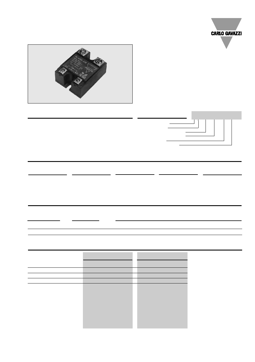
Industrial, 1-Phase PS, High dV/dt
Types RC 23 .. -D 06, RC 48 .. -D 12
RC 48 10 -D 12
2
Specifications are subject to change without notice (04.02.00)
RC 23 .. -D 06, RC 48 .. -D 12
Control voltage range
4 to 32 VDC
Pick-up voltage
4 VDC
Drop-out voltage
1 VDC
Reverse voltage
32 VDC
Input impedance
1 k
Response time pick-up
1/2 cycle
Response time drop-out
1/2 cycle
Input pulse, rise/fall time
100 µs
Insulation
Rated insulation voltage
Input to output
4000 VACrms
Rated insulation voltage
Output to case
4000 VACrms
Insulation resistance
Input to output
10
10
Insulation resistance
Ouput to case
10
10
Insulation capacitance
Input to output
8 pF
Insulation capacitance
Output to case
50 pF
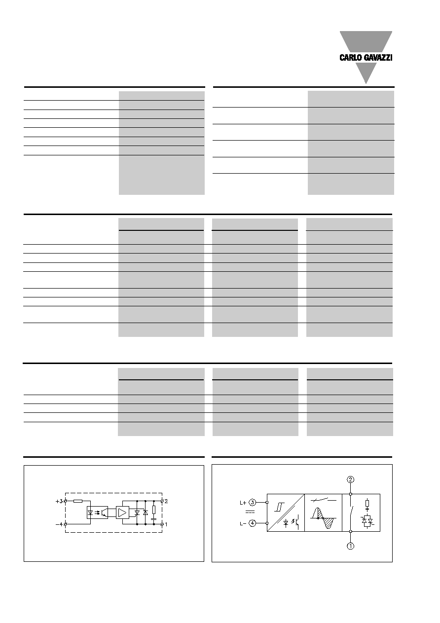
Wiring Diagram
Functional Diagram
Control
input
RC .. 10 -D ..
RC .. 25 -D ..
RC .. 50 -D ..
Operating temperature
-20∞ to +70∞C (-4∞ to +158∞F)
-20∞ to +70∞C (-4∞ to +158∞F)
-20∞ to +70∞C (-4∞ to +158∞F)
Storage temperature
-40∞ to +100∞C (-40∞ to +212∞F)
-40∞ to +100∞C (-40∞ to +212∞F)
-40∞ to +100∞C (-40∞ to +212∞F)
Junction temperature
125∞C (257∞F)
125∞C (257∞F)
125∞C (257∞F)
R
th
junction to case
2 K/W
1.25 K/W
0.65 K/W
R
th
junction to ambient
12.5 K/W
12 K/W
12 K/W
Thermal Specifications
RC .. 10 -D ..
RC .. 25 -D ..
RC .. 50 -D ..
Rated operational current AC1
10 Arms
25 Arms
50 Arms
Minimum operational current
100 mArms
100 mArms
100 mArms
Rep. overload current t=1 s
50 A
p
80 A
p
175 A
p
Non-rep. surge current t=20 ms 160 A
p
250 A
p
600 A
p
Off-state leakage current
@ rated voltage and frequency
5 mArms
5 mArms
5 mArms
I
2
t for fusing t=1-10 ms
130 A
2
s
310 A
2
s
1800 A
2
s
Critical dI/dt
100 A/µs
100 A/µs
100 A/µs
On-state voltage drop
@ rated current
1.6 Vrms
1.6 Vrms
1.6 Vrms
Critical dV/dt off-state
2 kV/µs
2 kV/µs
2 kV/µs
Output Specifications
Mains input/load output
Load output/mains input
Control
input
Line/load
Input Specifications
Specifications are subject to change without notice (04.02.00)
3
RC 23 .. -D 06, RC 48 .. -D 12
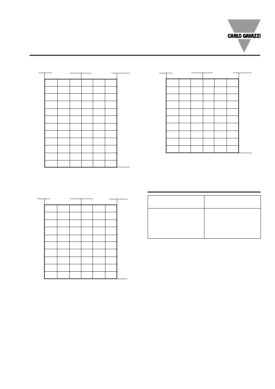
Heatsink Dimensions
(load current versus ambient temperature)
RC .. 10 -D ..
2.7
2.2
1.8
1.3
0.87
0.41
22
3.1
2.6
2.1
1.7
1.2
0.65
20
3.7
3.1
2.6
2
1.5
0.92
18
4.3
3.7
3.1
2.5
1.9
1.2
16
5
4.3
3.7
3
2.3
1.6
15
5.9
5.1
4.4
3.6
2.8
2.1
13
6.9
6
5.2
4.3
3.5
2.6
12
7.9
6.9
5.9
4.9
4
3
10
10.8
9.5
8.1
6.8
5.4
4.1
7
-
14.2
12.2
10.2
8.1
6.1
5
-
-
-
-
14.6
10.9
3
-
-
-
-
-
-
1
20
30
40
50
60
70
16
15
14
13
12
11
10
9
7
5
3
1
Load
current [A]
Thermal resistance
[K/W]
T
A
Ambient temp. [
∞
C]
Power
dissipation [W]
RC ..50 -D ..
T
A
Ambient temp. [
∞
C]
0.92
0.76
0.60
0.45
0.29
-
63
1.2
0.99
0.80
0.62
0.44
0.26
55
1.5
1.3
1.1
0.85
0.63
0.42
47
1.9
1.6
1.4
1.1
0.89
0.63
40
2.4
2.1
1.8
1.5
1.2
0.91
33
3
2.7
2.3
1.9
1.5
1.1
26
3.9
3.5
3
2.5
2
1.5
20
5.5
4.8
4.1
3.4
2.7
2.1
15
8.6
7.5
6.4
5.4
4.3
3.2
9
17.9
15.6
13.4
11.2
8.9
6.7
4
20
30
40
50
60
70
50
45
40
35
30
25
20
15
10
5
Power
dissipation [W]
Thermal resistance
[K/W]
Load
current [A]
RC .. 25 -D ..
25
22.5
20
17.5
15
12.5
10
7.5
5
2.5
Power
dissipation [W]
2
1.7
1.4
1
0.71
0.40 32
2.5
2.1
1.8
1.4
1
0.66
27
3.1
2.7
2.3
1.9
1.4
1
23
4.0
3.5
3
2.5
2
1.4
20
4.9
4.3
3.7
3.1
2.5
1.9
16
6.2
5.4
4.6
3.9
3.1
2.3
13
8.1
7.1
6.1
5.1
4
3
10
11.3
9.9
8.5
7.1
5.6
4.2
7
-
15.6
13.3
11.1
8.9
6.7
5
-
-
-
-
18.7
14
2
20
30
40
50
60
70
T
A
Ambient temp. [
∞
C]
Load
current [A]
Thermal resistance
[K/W]
Carlo Gavazzi Heatsink
(see Accessories)
No heatsink required
RHS 100 Assy
RHS 301 Assy
RHS 301 F Assy
Consult your distributor
Heatsink Selection
Thermal resistance
R
th s-a
> 12.5
K/W
3.0 K/W
0.8 K/W
0.25 K/W
< 0.25 K/W
Compare the value found in the current versus temperature
chart with the standard heatsink values and select the heat-
sink with the next lower value.
4
Specifications are subject to change without notice (04.02.00)
RC 23 .. -D 06, RC 48 .. -D 12
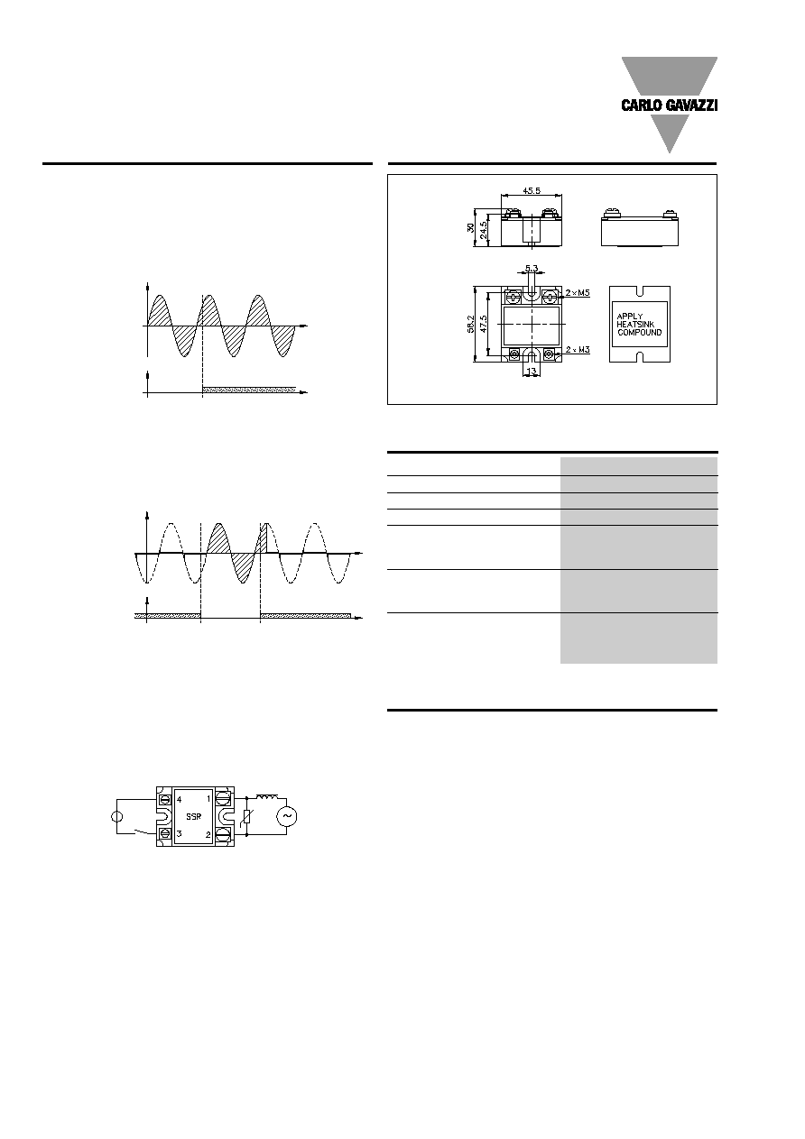
Applications
Timing
Initial turn-on
The line voltage must be pre-
sent at least 1 period before
the input voltage is applied.
Repetitive turn-on
The input voltage must be
lower than the drop out volt-
age limit at least 1 period be-
fore it is reapplied.
As transformers can have va-
rying stray inductances and
stray capacitances, it is al-
ways advisable to use external
overvoltage protection.
Varistor diameter:
20 mm
Varistor voltage for 240 V SSR:
250 VAC (RV 02)
Varistor voltage for 440 V SSR:
480 VAC (RV 05)
Overvoltage protection
Dimensions
Housing Specifications
Weight
Approx. 110 g
Housing material
Noryl GFN 1, black
Base plate
Aluminium
Potting compound
Polyurethane
Relay
Mounting screws
M5
Mounting torque
1.5 Nm
Control terminal
Mounting screws
M3 x 6
Mounting torque
0.5 Nm
Power terminal
Mounting screws
M5 x 6
Mounting torque
2.4 Nm
Accessories
Protection cover
Heatsinks
DIN rail adapter
Varistors
Fuses
Input
voltage
Load
Supply
voltage
** =
±
0.4 mm
*** =
±
0.5 mm
**
**
***
***
***
***
Line voltage
Output voltage
Input voltage
Min. 1 period
Input voltage
Min. 1 period
For further information refer
to "General Accessories".