Specifications are subject to change without notice (27.06.2006)
1
∑ AC semiconductor contactor
∑ Zero switching (RJ1A) or
instant-on switching (RJ1B)
∑ Direct copper bonding (DCB) technology
∑ LED-indication
∑ Cage clamp output terminals
∑ 2 input ranges: 4-32 VDC and 24-275 VAC/24-48VDC
∑ Operational ratings up to 75 AACrms and 600 VAC
1
∑ Non-repetitive voltage: Up to 1200 Vp
∑ Opto-isolation > 4000 VACrms
∑ Over-temperature safety option
2
∑ Integrated fan option
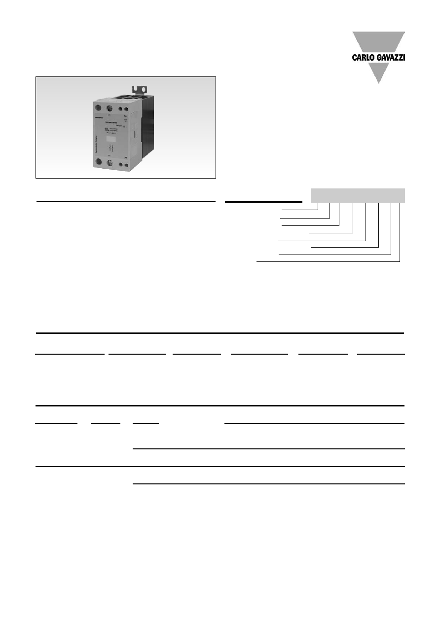
Product Description
Ordering Key
The SOLITRON Midi is a sin-
gle-phase Solid State
Contactor designed to replace
electro-mechanical contactors
in industrial heating and motor
applications, especially when
switching is frequent. The
product is ready to mount on
DIN-rail or chassis and comes
with integral heatsink. For cur-
rent rating of 75AACrms
(AC51) convection cooling is
used. The standard housing
dimensions enable straightfor-
ward replacement of alterna-
tive products and the terminal
layout allows both contactor
(E) and SSR (U) type connec-
tion. Cage clamp terminals
are used to ensure secure load
connection with cable up to
25mm
2
.
An LED indicates the status of
the control input. The superior
heat-transfer efficiency com-
bined with a robust power
management system make
this a high reliability product
that can meet the most strin-
gent functional requirements.
Solid State Relay
Number of poles
Switching mode
Rated operational voltage
Control voltage
Rated operational current
Terminal layout
Options
Solid State Relays
SOLITRON MIDI - With Integrated Heatsink
Types RJ1A, RJ1B
Type Selection
Switching
Rated operational
Control voltage
Rated operational
Terminal layout
Options
mode
voltage
1
current
A: Zero switching
23: 230 VACrms
D: 4-32
VDC
45: 45 AACrms
U: SSR
P: Over-temp.
B: Instant-on
60: 600 VACrms
A: 24-275 VAC/
50: 50 AACrms
E: Contactor
protection
2
switching
3
24-48 VDC
75: 75 AACrms
4
V: Integrated
Varistor
Rated opera-
Non-rep.
Control
Rated operational current
tional voltage
voltage
voltage
45 A
50 A
75 A (FAN+OTP)
2
230 VACrms
650 V
p
4 - 32 VDC
RJ1A23D45E
RJ1A23D50E
RJ1A23D75EP
RJ1A23D45U
RJ1A23D50U
24 - 275 VAC / 24 - 48 VDC
RJ1A23A45E
RJ1A23A50E
RJ1A23A75EP
RJ1A23A45U
RJ1A23A50U
600 VACrms
1200 V
p
4 - 32 VDC
RJ1A60D45E
RJ1A60D50E
RJ1A60D75EP
RJ1A60D45U
RJ1A60D50U
24 - 275 VAC / 24 - 48 VDC
RJ1A60A45E
RJ1A60A50E
RJ1A60A75EP
RJ1A60A45U
RJ1A60A50U
Notes
1
690 VACrms rated operational voltage available on request. Example: RJ1A69D45U
2
"P" suffix: Over-temperature protection (OTP), available with type "E" terminals only
3
Instant-on versions not available with AC control voltage
4
With integrated fan and over-temperature protection - fan will automatically switch on when necessary
Selection Guide
RJ 1 A 60 D 50 E P
2
Specifications are subject to change without notice (27.06.2006)
Thermal Specifications
RJ1A60D50E
General Specifications
RJ1.23..
RJ1.60..
Operational voltage range
24 to 265 VAC
42 to 660 VAC
Non-rep. peak voltage
650 V
p
1200 V
p
Operational frequency range
45 to 65 Hz
45 to 65 Hz
Power factor
0.5 @ 230 VACrms
0.5 @ 600 VACrms
Over-temperature alarm
I
max
50mADC
50mADC
U
max
50VDC
50VDC
Approvals
UL,cUL, CSA
UL, cUL, CSA
CE-marking
Yes
Yes
Pollution degree
2
2
RJ...D
RJ...A
Operating temperature
-30 to +70∫C (-22 to +158∞F)
-30 to +70∫C (-22 to +158∞F)
Storage temperature
-40 to +100∫C (-40 to +176∞F)
-40 to +100∫C (-40 to +176∞F)
Input Specifications
RJ1A...D
RJ1B..D
RJ1A...A
Control voltage range
4 - 32 VDC
4.5 - 32 VDC
24-275 VAC/24 - 48 VDC
Pick-up voltage
3.8 VDC
4.25 VDC
22 VAC/DC
Reverse voltage
32 VDC
32 VDC
n/a
Drop-out voltage
1.2 VDC
1.0 VDC
6 VAC/DC
Maximum input current
12 mA
15 mA
17 mA
Response time pick-up
1/2 cycle
1 ms
1 cycle
Response time drop-out
1/2 cycle
1 cycle
1 cycle
Output Specifications
RJ..45
RJ..50
RJ..75
(With integrated fan)
Rated operational current
AC51 @Ta=25∫C
45 AACrms
50 AACrms
75 AACrms
AC53a @Ta=25∞C
20 AACrms
30 AACrms
30 AACrms
Min. operational current
150 mAACrms
150mAACrms
150mAACrms
Rep. overload current t = 1s
< 150 AACrms
<200 AACrms
<200 AACrms
Non rep. surge current Tj(init.)
= 25∫C and t = 10 ms
1150 A
p
1900 A
p
1900 A
p
Off-state leakage current @
rated voltage and frequency
< 3 mArms
< 3 mArms
< 3 mArms
I
2
t for fusing t = 10 ms
6600 A
2
s
18000 A
2
s
18000 A
2
s
Critical dI/dt
100 A/µs
100 A/µs
100 A/µs
On-state voltage drop @ rated current
1.6 Vrms
1.6 Vrms
1.6 Vrms
Critical dV/dt off-state
500 V/µs
500 V/µs
500 V/µs

Specifications are subject to change without notice (27.06.2006)
3
RJ1A60D50E
Applications
Two single pole relays in
3-phase application
Delta and star.
(Economy Switch)
L
1
L
2
L
3
3 single pole relays in
3-phase application
Delta, Star, Star with neutral
L
1
L
2
L
3
N
All dimensions in mm
Terminal Layout
Relay On
Relay On
Alarm On
Alarm On
RJ1A.....E
RJ1A.....U
Dimensions
1
L1
5
A3
3
A1
2
T1
6
A4
4
A2
5
A2
3
A1
2
T1
6
A4
1
L1
4
A3
Derating Curve
Dissipation Curve
Surrounding temp. (þC)
Load current (AACrms)
20
30
40
50
60
70
20
30
40
50
60
70
80
50A
75A
45A
0
10
20
30
40
50
60
70
80
AACrms
W
10
20
30
40
50
60
70
0
75A
50A
45A
Surrounding temp. (∞C)
RJ1...75EP
RJ1...50
RJ1...45

RJ1A60D50E
Derating vs spacing curves
4
Specifications are subject to change without notice (27.06.2006)
RJ1 ..45
RJ1 ..50
Surrounding Temp. (∞C)
Surrounding Temp. (∞C)
Load current (AACrms)
Load current (AACrms)
RJ1 ..75
Load current (AACrms)
46
44
42
40
38
36
34
32
30
28
26
24
22
20
52
50
48
46
44
42
40
38
36
34
32
30
28
26
24
76
72
68
64
60
56
52
48
44
40
36
20 25 30 35 40 45 50 55 60 65 70
20 25 30 35 40 45 50 55 60 65 70
20 30
40
50
60
70
6.0mm
3.0mm/ 0.0mm
22.5mm/ 10.0mm
6.0mm
3.0mm/ 0.0mm
22.5mm/ 10.0mm
6.0mm
3.0mm/ 0.0mm
22.5mm/ 10.0mm
Surrounding
Temp. (∞C)

Specifications are subject to change without notice (27.06.2006)
5
Weight
RJ MIDI
Approx. 430g
RJ MIDI w. fan
Approx. 460g
Housing material
PBT Flame retardant
Control terminal cable size
Min
1 x 0.5 mm
2
(1 x AWG20)
Max
1 x 4.0 mm
2
(1 x AWG12) or
2 x 2.5 mm
2
(2 x AWG14)
Mounting torque max.
0.6 Nm with Posidrive 0 bit
Control terminal screws
M3
Power terminal cable size
Min
1 x 4 mm
2
(1 x AWG12)
Max
1 x 25 mm
2
(1 x AWG3) or
2 x 10 mm
2
(2 x AWG6)
Mounting torque max.
2.5 Nm with Posidrive 2 bit
Power terminal screws
M5
RJ1A60D50E
Insulation
Rated insulation voltage
Input to output
4000 VACrms
Output to case
4000 VACrms
Housing Specifications
Over-temperature Protection (Option: ...P)
Connection Examples
~
~
2T1
1L1
3A1
5A3
4A2
6A4
~
~
+
-
24-275 VAC
Example (AC control with fan)
RJ1A60A75EP
Note: Over-temperature
alarm output
not available in this option
Fan supply input
24VDC, 200mA
LOAD
24-275 VAC
SSR Input*
Green LED
Red LED
SSR Output
Alarm status
Over-temperature
detection
20ms
Over-temperature protection is ON
SSR output disabled
Over-temperature
Sensing
Closed
Open
*After over-temperature condition is removed, SSR can be reset by switching OFF the control input for more than 20 ms and switching back ON: this will
*
switch ON the SSR output
~
~
LOAD
+
+
Over-temperature alarm output
Max voltage: 50VDC
Max current: 50mA
4-32VDC
Example (DC control with fan)
RJ1A60D75EP
0V
Fan supply Input
24 VDC, 200mA
-
2T1
1L1
3A1
5A3
4A2
6A4
~
~
Over-temperature alarm output
Max voltage: 50VDC
Max current: 50mA
24-275 VAC
Example (AC control without fan)
RJ1A60A50EP
+
-
2T1
1L1
3A1
5A3
4A2
6A4
24-275 VAC
LOAD
~
~