Rated operational
Non-rep. voltage
Control input
Supply voltage
Rated operational
voltage
current (50 A)
230VACrms
650Vp
0 - 10VDC
24VAC/DC
RJ1P23V50E
4 - 20mA
RJ1P23I50E
480VACrms
1200Vp
0 - 10VDC
24VAC/DC
RJ1P48V50E
4 - 20mA
RJ1P48I50E
600VACrms
1200Vp
0 - 10VDC
24VAC/DC
RJ1P60V50E
4 - 20mA
RJ1P60I50E
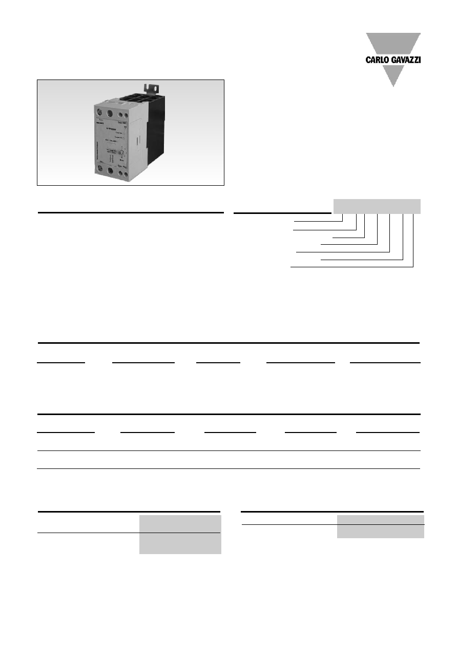
Solid State Relay
Number of poles
Switching mode (Proportional)
Rated operational voltage
Control input type
Rated operational current
Terminal layout
Specifications are subject to change without notice (27.06.2006)
1
∑ AC semiconductor contactor
∑ Multi-function - 5 selectable modes of operation:
Phase Angle, Distributed Full Cycle and Burst Control
(1, 3 and 10s)
∑ Direct copper bonding (DCB) technology
∑ LED-indication for control and load status
∑ Operational ratings up to 50 AACrms and 600 VAC
∑ 4-20mA or 0-10V control input
∑ Built-in varistor
∑ Non-repetitive voltage: Up to 1200Vp
∑ Opto-isolation > 4000VACrms
∑ Cage clamp terminals
∑ IP20 protection
Product Description
Ordering Key
The Solitron Midi Analog
Switching is a single-phase
SSR that provides proportional
output power in relation to the
control signal level applied.
This microprocessor-based
device provides for 5 different
switching modes integrated
into one package. A selector
switch on the front of the
device is used for the selection
of the preferred mode of oper-
ation, i.e., either Phase Angle,
Distributed Full Cycle or Burst
Control. This multi-function
selection makes this device
ideal for the control of a variety
of loads, including heaters and
lamps. The control signal can
be either 4 - 20mA or 0 -
10VDC. 4mA or 0V correspond
to zero output power, whilst
20mA or 10VDC correspond to
full output power.
The product is ready to mount
on DIN-rail or chassis and
comes with integral heatsink.
Solid State Relays
SOLITRON MIDI Multi-Function Analog Switching
Type RJ1P
Type Selection
Switching
Rated operational
Control
Rated operational
Terminal
mode
voltage
input
current
layout
P: Proportional
23: 230VACrms
V: 0 - 10VDC
50: 50AACrms
E: Contactor
Output
48: 480VACrms
I: 4 - 20mA
60: 600VACrms
Selection Guide
RJ 1 P 48 V 50 E
Thermal Specifications
Operating temperature
-20 to +60∫C (-4 to +140 ∞F)
Storage temperature
-40 to +100∫C (-40 to +212 ∞F)
Insulation
Rated insulation voltage
Input to output
4000 VACrms
Output to case
4000 VACrms

RJ1P23...
RJ1P48...
RJ1P60...
Operational voltage range
90 to 265VAC
200 to 550VAC
410 to 660VAC
Non-rep. peak voltage
650V
p
1200V
p
1200V
p
Operational frequency range
45 to 65Hz
45 to 65Hz
45 to 65Hz
Output power
0 to 99%
0 to 99%
0 to 99%
Power factor
0.9 @ 230VACrms
0.9 @ 480VACrms
0.9 @ 600VACrms
Load status indication
Red LED
Red LED
Red LED
Output power resolution
MODE 1
Phase Angle
1/300 @ 50Hz, 1/300 @ 60Hz
MODE 2
Full Cycle
1/64 @ 50Hz, 1/64 @ 60Hz
MODE 3
Burst with 1s period
1/50 @ 50Hz, 1/60 @ 60Hz
MODE 4
Burst with 3s period
1/150 @ 50Hz, 1/180 @ 60Hz
MODE 5
Burst with 10s period
1/500 @ 50Hz, 1/600 @ 60Hz
Approvals UL,
cUL
CE-marking
Yes
RJ1P..I...
Current controlled input
Control current range
4 - 20mA
Max. allowable input current
50mA
Pick up current
4.2mA
Drop out current
3.9mA
Control status indication
Green LED
Reverse polarity protected
Yes
Voltage drop
10VDC @ 20mA
RJ1P..V...
Voltage controlled input
Supply voltage range, Vss
20 - 28VAC/DC
Supply current
18mA @ 24VDC
23mA @ 24VAC
Control voltage range, Vcc
0 - 10VDC
Control input current
0.1mA @ 10VDC
Reverse polarity protected
Yes
Pick up voltage
0.5VDC
Drop out voltage
0.05VDC
Control status indication
Green LED
2
Specifications are subject to change without notice (27.06.2006)
RJ1P
Input Specifications
General Specifications
Weight
Approx. 430 g
Housing material
PBT Flame retardant
Control terminal cable size
Min
1 x 0.5 mm
2
(1 x AWG20)
Max
1 x 4.0 mm
2
(1 x AWG12) or
2 x 2.5 mm
2
(2 x AWG14)
Mounting torque max.
0.6 Nm Posidriv 0 bit
Control terminal screw
M3
Power terminal cable size
Min
1 x 4 mm
2
(1 x AWG12)
Max
1 x 25 mm
2
(1 x AWG3) or
2 x 10 mm
2
(2 x AWG6)
Mounting torque max.
2.5 Nm Posidriv 2 bit
Power terminal screw
M5
Housing Specifications
Output Specifications
Rated operational current
AC51 @Ta=25∫C
50AACrms
Min. operational current
150mAACrms
Rep. overload current t=1 s
(Tj init.=25∞C)
< 200AACrms
Non-rep. surge current t=10 ms
(Tj init.=25∞C)
1900A
p
Off-state leakage current,
@ rated voltage and frequency
< 3 mArms
I
2
t for fusing t=10 ms
18000A
2
s
On-state voltage drop @
rated current
1.6Vrms
Critical dV/dt off-state
1000V/µs
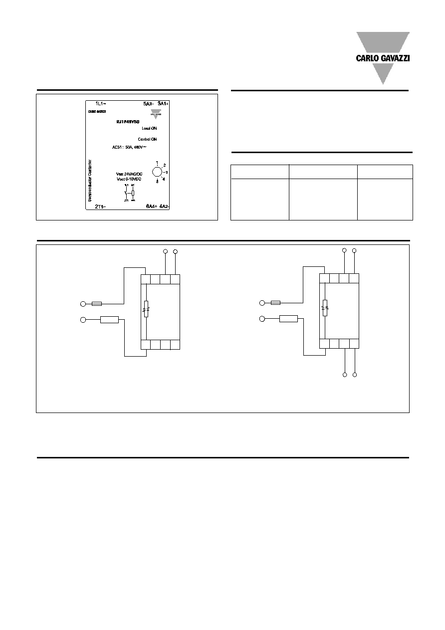
Example: RJ1P48I50E
Example: RJ1P48V50E
~
~
-
+
LOAD
4 - 20mA
2T1
1L1
5A3 3A1
4A2
6A4
~
~
LOAD
+
10VDC
2T1
1L1
5A3 3A1
4A2
6A4
+
0V
24VDC/AC
-
0V
-
Specifications are subject to change without notice (27.06.2006)
3
RJ1P
Connection Examples
3A1 - 5A3: Control input current
3A1 - 5A3: Control input voltage, Vcc
4A2 - 6A4: Supply input voltage, Vss
LED INDICATION
The top Red LED indicates the
load status. It goes ON when-
ever the load is activated. The
Green LED gives indication of
the status of the control input.
Upon application of control
current (for the RJ1P..I...) to
terminals A1-A3, the Green
LED will be dimly lit, with its
intensity increasing with an
increase in control current.
For the RJ1P..V..., the Green
LED will be ON (flickering)
upon application of the supply
voltage to terminals A2 - A4.
Once a control voltage is
applied to terminals A1 - A3,
the Green LED will be fully ON,
if greater than a threshold volt-
age (approx. 0.5V). Note that
the first time the device (volt-
age control version) is to be
activated, the mains voltage
has to be present for the
Green LED to indicate the
control status.
Terminal Layout
Mode Selection
Operation
MODE
Transfer characteristics
Control
Control
Output
Current (mA)
Voltage (VDC)
Power (%)
4
0
0
8
2.5
25
12
5
50
16
7.5
75
20
10
99
Output power as a function of control input
MODE 1
Phase Angle Switching
MODE 2
Distributed Control
MODE 3
Burst Switching (1 sec. period)
MODE 4
Burst Switching (3 sec. period)
MODE 5
Burst Switching (10 sec. period)
MODE 1: The Phase Angle
switching mode works in
accordance with the phase
angle control principle, i.e. the
output switching point in the
AC sine wave depends on the
signal level applied at the
input. The relay switches off
everytime the output current
crosses zero.
MODE 2: The Distributed
mode provides a number of
full cycles, evenly distributed
over a fixed period of 1.28s @
50Hz (1.07s @ 60Hz), depend-
ing on the control input.
MODE 3, 4, 5: The Burst
Switching mode generates a
number of full cycles, depend-
ing on the control input over
fixed periods of 1s, 3s or 10s
for MODES 3, 4 and 5 respec-
tively.
Modes 2, 3, 4 and 5 use the
zero switching principle, thus
ensuring a reduced level of
radiated and wire-conducted
noise. The Distributed and
Burst Switching modes are not
recommended for light control
due to light-flickering.
Note: For the RJ1P..V..., it is possible to have the ground terminals of the supply and control power supplies used commoned. In the case, this common
ground is connected either to terminal A2 or terminal A3. This is only applicable when a 24 VDC supply voltage is used. There should be no external direct
link from terminal A2 to Terminal A3.
4
Specifications are subject to change without notice (27.06.2006)
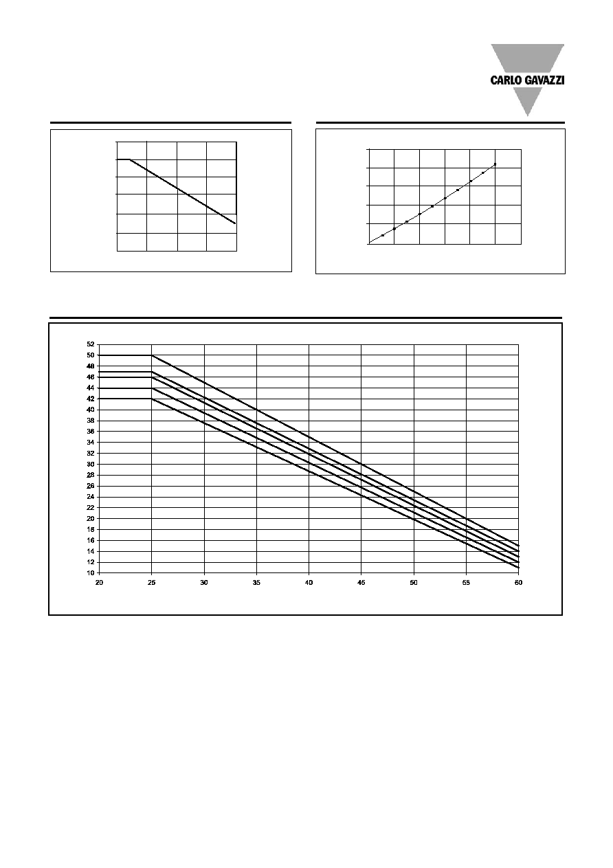
Derating vs. Spacing Curves
RJ1P
Derating Curve
Dissipation Curve
Load Current
(AACrms)
Surrounding temp. (Deg. C)
20
30
40
50
60
20
30
40
50
60
10
0
0
10
20
30
40
50
60
AACrms
W
10
20
30
40
50
0
50A
Note: Based on 100% output power
Surrounding temp. (∞C)
Note: Based on 100% output power
22.5mm
10.0mm
6.0mm
3.0mm
0.0mm
Load Curr
ent (AACrms)
Specifications are subject to change without notice (27.06.2006)
5
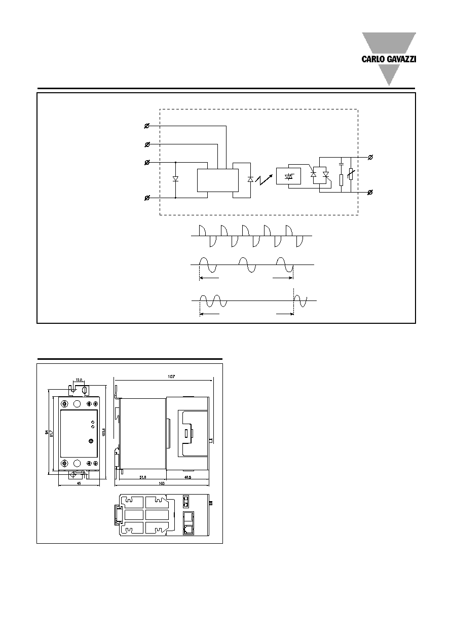
Dimensions
Functional Diagram
IC
A2 (-)
A4 (+)
A3 (-)
A1 (+)
Supply
input
Control
input
1 period = 64 cycles
1 period = 1s, 3s or 10s
RJ1P
Note: A2, A4 used only for voltage control version
MODE 1
Phase Angle
MODE 2
Distributed Full Cycle
MODE 3, 4, 5
Burst 1s, 3s, 10s
All dimensions in mm.