 | –≠–ª–µ–∫—Ç—Ä–æ–Ω–Ω—ã–π –∫–æ–º–ø–æ–Ω–µ–Ω—Ç: RJ3A60D25 | –°–∫–∞—á–∞—Ç—å:  PDF PDF  ZIP ZIP |
Specifications are subject to change without notice (12.07.2006)
1
∑
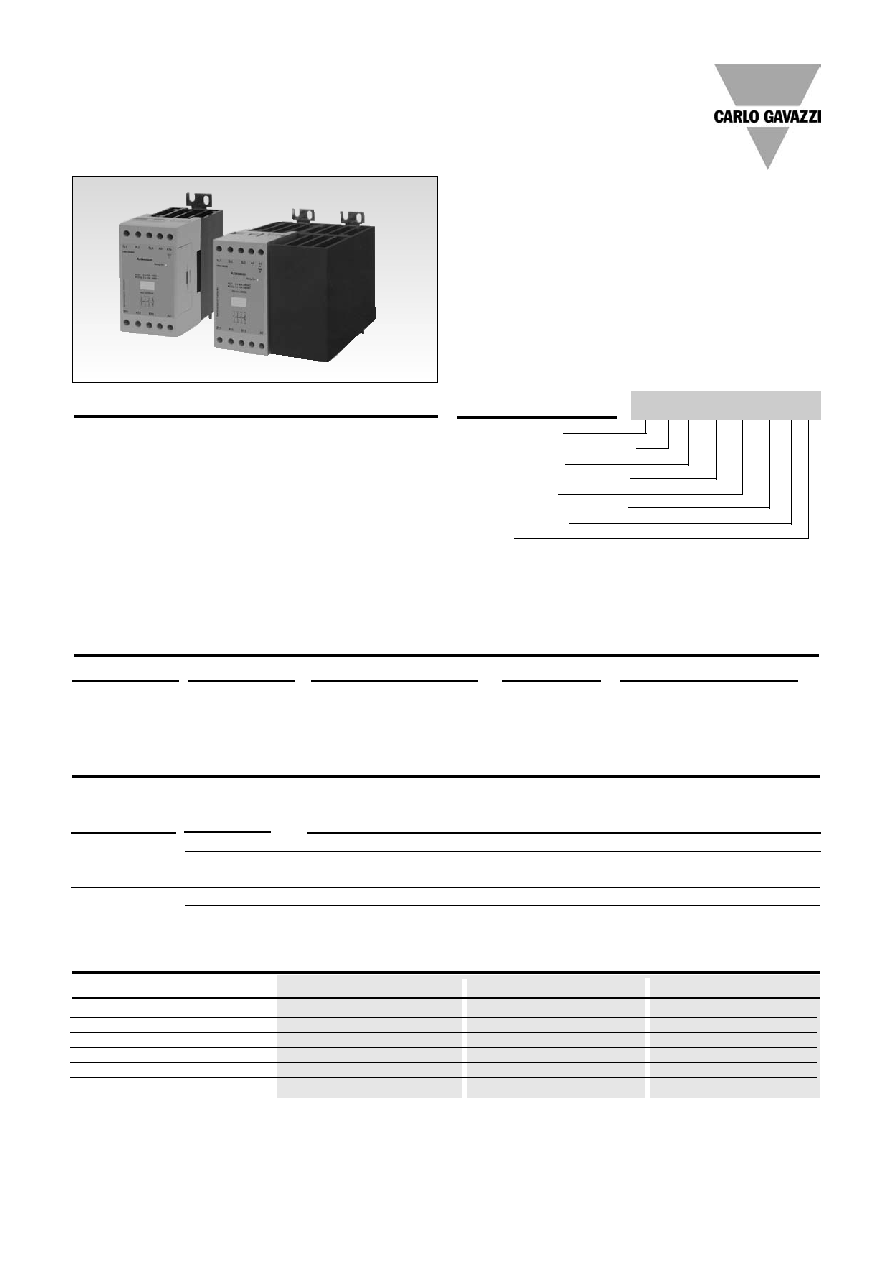
AC Semiconductor contactor
∑
Two and three pole switching types
∑
Direct copper bonding (DCB) technology
∑
LED indication
∑
Integrated over-voltage protection
∑
Housing free of moulding mass
∑
2 Input ranges: 5 ≠ 32 VDC and 24-275VAC/24-190VDC
∑
Operational ratings: up to 3x32AAC, 600VAC
∑
Non repetitive peak voltage: Up to 1200V
p
∑
Opto-isolation > 4000 VAC
rms
Product Description
Ordering Key
This product is designed in
such a way as to replace elec-
tro-mechanical contactors,
especially when switching is
frequent. It has an integrated
heatsink and over-voltage pro-
tection. The heatsink is
moved to the back for optimal
space saving in the panel and
easy wire mounting at the front
of the relay.
The relay with antiparallel
thyristor output is the most
widely used industrial SSR
due to its multiple application
possibilities and robust con-
struction. This relay can be
used for resistive and induc-
tive loads.
The zero switching relay
switches ON when the sinu-
soidal curve crosses zero and
switches OFF when the cur-
rent crosses zero. A green and
a red LED give status of the
control input and alarm
respectively.
Solid state relay
Number of switching poles
Switching mode
Rated operational voltage
Control voltage
Rated operational current
Terminal Layout
Options
Solid State Relays
Industrial, Rear Integrated Heatsink
3-Phase w LED
Types RJ2A, RJ3A
Type selection
Switching poles
Switching mode
Rated operational voltage
Control voltage
Rated operational current
RJ2: 2 poles
A: Zero switching
22: 220 VACrms
D: 5 - 32 VDC
20: 3 x 20 AAC
rms
(RJ3A)
RJ3: 3 poles
60: 600 VACrms
A: 24 - 275 VAC/
25: 3 x 25 AAC
rms
(RJ2A/RJ3A)
24 - 190 VDC
32: 3 x 32 AAC
rms
(RJ2A/RJ3A)
Rated operational
Control voltage
Rated operational current
voltage
2-Pole switching/1-Pole direct
3-Pole switching
3x25A (MIDI)
3x32A (POWER)
3x20A (MIDI)
3x25A (POWER) 3x32A (MIDI)
4
220 VACrms 5 - 32 VDC
RJ2A22D25
RJ2A22D32
RJ3A22D20
RJ3A22D25
RJ3A22D32EP
24 - 275 VAC/
RJ2A22A25E
RJ2A22A32E
RJ3A22A20E
RJ3A22A25E
RJ3A22A32EP
24 - 190 VDC
600 VACrms
5 - 32 VDC
RJ2A60D25
RJ2A60D32
RJ3A60D20
RJ3A60D25
RJ3A60D32EP
24 - 275 VAC/
RJ2A60A25E
RJ2A60A32E
RJ3A60A20E
RJ3A60A25E
RJ3A60A32EP
24 - 190 VDC
Selection Guide
Options
RJ 3 A 60 D 32 E P
Notes
1 Basic models with DC control input (without over-temperature protection or fan) have both U-type and E-type terminal connections
2 All models with over-temperature protection option (suffix "P") or AC control input are only available with type "E" terminals
3 Fan switching is internally controlled. Fan requires an external supply connected to the fan supply input(s)
4 With integrated fan and over-temperature protection - fan will automatically switch on when necessary
MIDI
POWER
Model Type
Alarm LED indication
Alarm connections
Fan supply input
DC control
No
No
No
DC control + OTP
Yes
Yes
No
DC control + OTP + Fan
Yes
Yes
Yes
AC control
No
No
No
AC control + OTP
Yes
Yes
No
AC control + OTP + Fan
Yes
No
Yes
2
Specifications are subject to change without notice (12.07.2006)
RJ3A60D20
General Specifications
Operating Temperature
-30 to +70∫C (-22 to +158∞F)
Storage temperature
-40 to +80∫C (-40 to +178∞F)
Input Specifications
RJ..D..
RJ..A..
Control voltage range
5 - 32 VDC
24-275 VAC/ 24-190 VDC
Pick-up voltage
4.7 VDC
22 VAC/ VDC
Reverse voltage
32 VDC
N/A
Drop-out voltage
1.2 VDC
6 VAC/ 6VDC
Maximum input current
24 mA
15mA
Response time pick-up
<1 cycle
<1 cycle
Response time drop-out
<1 cycle
<1 cycle
Output Specifications
Weight
MIDI
Approx. 380 g
MIDI + FAN
Approx. 415 g
POWER
Approx. 680 g
Housing material
PBT, Flame Retardant
Conductors
Size
0.5...4.0 mm
2
(AWG 20...12)
0.5...2x2.5 mm
2
(AWG 20...2x14)
Mounting torque max.
0.6 Nm with Posidrive 0 bit
Terminal screws
M3
Insulation
Thermal Specifications
Rated insulation voltage
Input to output
4000 VACrms
Output to case
4000 VACrms
Housing Specifications
RJ..22..
RJ..60..
Operational voltage range
24 - 280 VAC
48 - 660 VAC
Non-rep. peak voltage
650 V
p
1200 V
p
Operational frequency range
45 - 65 Hz
45 - 65 Hz
Power factor
0.5 @ 230 VACrms
0.5 @ 600 VACrms
Internal Varistor
Yes
Yes
Approvals
UL, cUL, CSA
UL, cUL, CSA
CE-marking
Yes
Yes
Pollution degree
2
2
2-Pole switching/1-Pole direct
3-Pole switching
RJ2A..25 (MIDI) RJ2A..32 (POWER)
RJ3A..20 (MIDI)
RJ3A..25 (POWER)
RJ3A..32 (MIDI)*
Rated operational current
AC51
@Ta=25∫C
3 x 25 A
3 x 32 A
3 x 20 A
3 x 25 A
3 x 32 A
AC53a @Ta=25∞C
3 x 15 A
3 x 15 A
3 x 15 A
3 x 15 A
3 x 15 A
Min. opertional current
150mA
150mA
150 mA
150mA
150mA
Rep. overload current t=1s
<125 A
<125 A
<125 A
<125 A
<125 A
Non rep. surge current
Tj(init.)= 25∫C and t=10ms
580 Apk
580 Apk
580 Apk
580 Apk
580 Apk
Off-state leakage current
@ rated voltage & frequency
< 3 mA
< 3 mA
< 3 mA
< 3 mA
< 3 mA
I
2
t for fusing (t = 1-10 ms)
1680 A
2
s
1680 A
2
s
1680 A
2
s
1680 A
2
s
1680 A
2
s
Critical dI/dt
50 A/µs
50 A/µs
50 A/µs
50 A/µs
50 A/µs
On-state voltage drop
@ rated current
1.6 Vrms
1.6 Vrms
1.6 Vrms
1.6 Vrms
1.6 Vrms
Critical dV/dt off-state
500 V/µs
500 V/µs
500 V/µs
500 V/µs
500 V/µs
* With integrated fan and over-temperature protection

1
0
2
.
5
Specifications are subject to change without notice (12.07.2006)
3
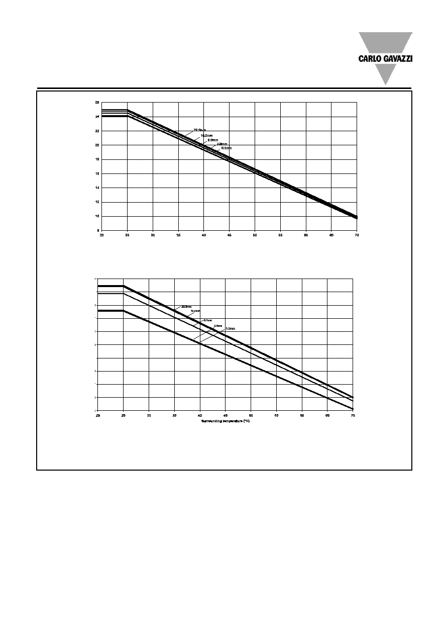
Note: dotted line indicates UL rating for RJ3...20
All dimensions in mm
All dimensions in mm
RJ3A60D20
Dimensions
Derating Curve
Dissipation Curve
RJ2A..32
RJ3A..25
MIDI
POWER
Load Curr
ent per phase (A)
T
o
tal Power dissipation (W)
Surrounding temperature (∞C)
RJ3..32
RJ2..32
RJn..25
RJ3..20
Load Current per phase (A)
RJ3..32
RJ2..32
RJ2..25
0 5 10 15 20 25 30 35 40
20 25 30 35 40 45 50 55 60 65 70
RJ3..20
RJ3..25
RJ2A..25*
RJ3A..20*
RJ3A..32
* without fan
20
00
80
60
40
20
0
36
34
32
30
28
26
24
22
20
18
16
14
12
10
8
6
Over-temperature Protection (Option: ...P)
SSR Input*
Green LED
Red LED
SSR Output
Alarm status
Over-temperature
detection
20ms
Over-temperature protection is ON
SSR output disabled
Over-temperature
Sensing
Closed
Open
*After over-temperature condition is removed, SSR can be reset by switching OFF the control input for more than 20 ms and switching back ON: this will
*
switch ON the SSR output

4
Specifications are subject to change without notice (12.07.2006)
RJ3A60D20
Derating vs. Spacing Curves
RJ2...25
RJ2...32
Surrounding Temp. (∞C)
Surrounding Temp. (∞C)
Load Curr
ent per Phase (A)
Load Curr
ent per Phase (A)
RJ3...20
Surrounding Temp. (∞C)
Load Curr
ent per Phase (A)
Specifications are subject to change without notice (12.07.2006)
5
RJ3A60D20
Derating vs. Spacing Curves (cont.)
RJ3...25
RJ3...32EP
Surrounding Temp. (∞C)
Surrounding Temp. (∞C)
Load Curr
ent per Phase (A)
Load Curr
ent per Phase (A)
6
Specifications are subject to change without notice (12.07.2006)
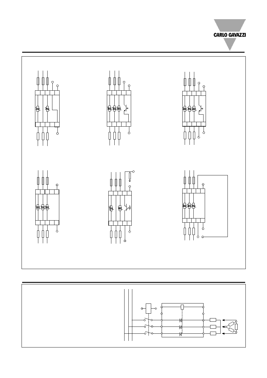
Connection Examples
5-32VDC
A2
3
L2
5
L3
A1
1
L1
4
T2
6
T3
2
T1
A2
0V
LOAD
0V
DC Control Input
Example: RJ2A60D25
24-275VAC or
+24-190VDC
3
L2
5
L3
A1
1
L1
4
T2
6
T3
2
T1
A2
24-275VAC
or 0VDC
LOAD
24-275VAC or
+24-190VDC
A3
3
L2
5
L3
A1
1
L1
4
T2
6
T3
2
T1
A2
24-275VAC
or 0VDC
LOAD
A4
+ -
Fan supply input +24VDC, 65mA
5-32VDC
Over-temperature alarm output
Max. voltage: 50 VDC
Max. current: 50mA
A3
3
L2
5
L3
A1
1
L1
4
T2
6
T3
2
T1
A2
0V
LOAD
DC Control Input +
over-temperature protection
Example: RJ3A60D20EP
5-32VDC
Over-temperature alarm output
Max. voltage: 50 VDC
Max. current: 50mA
A3
3
L2
5
L3
A1
1
L1
4
T2
6
T3
2
T1
A2
0V
LOAD
A4
Fan Supply input +24VDC, 65mA
DC Control Input + Fan +
over-temperature protection
Example: RJ3A60D32EP
AC Control Input
Example: RJ3A22A20E
AC Control Input + fan +
over-temperature protection
Example: RJ3A22A32EP
AC Control Input +
over-temperature protection
Example: RJ2A22A25EP
24-275VAC or
+24-190VDC
Over-temp. alarm output
to PLC (PNP)
50mA max
A3
3
L2
5
L3
A1
1
L1
4
T2
6
T3
2
T1
A2
24-275VAC
or 0VDC
LOAD
A4
+Vcc supply
(50V max)
Applications
L1
L3
L2
T2
A1
A2
L1
L2
L3
+A1
1
6
4
2
5
3
Safety Part
Control Part
Star
Connection
Delta
Connection
T1
T3
A2
Safety
When using a semiconductor contactor, the
electric configuration is split into a safety part
and a control part. In the safety part the isolation
of the load from the mains is assured by insert-
ing switchgear that provides galvanic isolation
from the power supply. A contactor or isolator
can be mounted in series with the Solid State
Relay to achieve this isolation. The contactor
can be a very economical type as the switching
is done by the Solid State Relay.
RJ3A60D20