Rated operational
Non-rep. voltage
Control voltage
Supply voltage
Alarm output
Rated operational
voltage
type
current
50 A
230 VACrms
650 Vp
4 - 32 VDC
24 VDC
NPN, NO
RJCS1A23D50EPNO
PNP, NO
RJCS1A23D50EPPO
600 VACrms
1200 Vp
4 - 32 VDC
24 VDC
NPN, NO
RJCS1A60D50EPNO
PNP NO
RJCS1A60D50EPPO
Solid State Relay
Current Sensing
Number of poles
Switching mode
Rated operational voltage
Control voltage
Rated operational current
Terminal layout
Over-temperature protection
Alarm output type
Specifications are subject to change without notice (27.06.2006)
1
∑ AC semiconductor contactor
∑ Integrated under current monitoring
∑ Zero switching (RJCS1A)
∑ Direct copper bonding (DCB) technology
∑ LED-indication
∑ Cage clamp output terminals
∑ 4-32 VDC control input
∑ Operational ratings up to 50 AACrms and 600 VAC
∑ Local and remote alarm status
∑ Set-point adjustable
∑ Time delay adjustable
∑ Local and remote setup
Product Description
Ordering Key
The SOLITRON Midi Current
Sensing is a compact, single-
phase SSR that is sensitive to
variations in load conditions in
industrial heating applications.
This microprocessor-based
device is ideal for detection of
partial load failure and to
ensure the highest process
quality. Current sensing is inte-
grated inside to eliminate the
need to install an external cur-
rent transformer. A membrane
"button" on the front is used to
effect a simple "teach in" of the
current setpoint. Alarm delay
time is set by a potentiometer.
A drop
in setpoint current of
more than
13%
will trigger an
open collector alarm. Up to 50
alarm outputs can be connect-
ed in parallel to a standard PLC
input. Typical conditions that
can be detected are heater
break or open-circuit, blown
fuse, semiconductor short-cir-
cuit and faulty power connec-
tion.
Device over-temperature pro-
tection is integrated as a stan-
dard feature.
The product is ready to mount
on DIN-rail or chassis and
comes with integral heatsink.
The standard housing dimen-
sions enable straightforward
replacement of alternative
products.
Solid State Relays
SOLITRON MIDI Current Sensing
Type RJCS
Type Selection
Switching
Rated operational Control
Rated operational Terminal
Protection
Alarm output
mode
voltage
voltage
current
layout
type
A: Zero switching 23: 230 VACrms
D: 4 - 32 VDC 50: 50 AACrms
E: Contactor P: Over-temp.
NO: NPN, Normally open
60: 600 VACrms
protection
PO: PNP, Normally open
Selection Guide
RJ CS 1 A 60 D 50 E P NO

Rated operational current
AC51 @Ta=25∫C
50 AACrms
AC53a @Ta=25∞C
30 AACrms
Min. TEACH current
8 AACrms
Min. partial load current
1.3 AACrms
Rep. overload current t = 1s
< 200 AACrms
Non rep. surge current
Tj(init.) = 25∫C and t = 10 ms
1900 Ap
Off-state leakage current @
rated voltage and frequency
< 3 mArms
I
2
t for fusing t = 10 ms
18000 A
2
s
On-state voltage drop @
rated current
1.6 Vrms
Critical dV/dt off-state
1000 V/µs
2
Specifications are subject to change without notice (27.06.2006)
RJCS
Input Specifications
Supply Specifications
Output Specifications
Control voltage range
4 - 32 VDC
Pick-up voltage
3.8 VDC
Reverse voltage
32 VDC
Drop-out voltage
1.2 VDC
Maximum control input current
1.5 mA
Response time pick-up
1/2 cycle
Response time drop-out
1/2 cycle
Thermal Specifications
Operating temperature
-20 to +60∫C (-4 to +140 ∞F)
Storage temperature
-40 to +100∫C (-40 to +212 ∞F)
Weight
Approx. 380 g
Housing material
PBT Flame retardant
Control terminal cable size
Min
1 x 0.5 mm
2
(1 x AWG20)
Max
1 x 4.0 mm
2
(1 x AWG12) or
2 x 2.5 mm
2
(2 x AWG14)
Mounting torque max.
0.6 Nm Posidriv 0 bit
Control terminal screws
M3
Power terminal cable size
Min
1 x 4 mm
2
(1 x AWG12)
Max
1 x 25 mm
2
(1 x AWG3) or
2 x 10 mm
2
(2 x AWG6)
Mounting torque max.
2.5 Nm Posidriv 2 bit
Power terminal screws
M5
Housing Specifications
Insulation
Rated insulation voltage
Input to output
4000 VACrms
Output to case
4000 VACrms
General Specifications
Alarm Specifications
Output current, i
o
50 mADC
Output voltage
NPN
1 + 0.15i
o
PNP
Vcc - 1 - 0.15i
o
No. of outputs in parallel
50
Power supply voltage, Vcc
24 VDC ± 15%
Max. supply current
22 mA (per device)
Max. PLC current @ 24VDC
275 µA (per device)
durning normal conditions
RJCS1.23..
RJCS1.60..
Operational voltage range
24 to 265 VAC
42 to 660 VAC
Non-rep. peak voltage
650 V
p
1200 V
p
Operational frequency range
45 to 65 Hz
45 to 65 Hz
Measuring range
8-50 AACrms
8-50 AACrms
Power factor
0.5 @ 230 VACrms
0.5 @ 600 VACrms
Approvals
UL, cUL
CE-marking
Yes
Supply status indication
Green LED, half intensity
Control status indication
Green LED
Over-temperature alarm trip indication
Red LED, intermittent
Alarm indication (excpect for over-temperature trip)
Red LED
~
~
LOAD
+
+
4-32VDC
0V
24 VDC
-
2T1
1L1 5A3 3A1
4A2
6A4
Alarm/Remote
Specifications are subject to change without notice (27.06.2006)
3
RJCS
Derating Curve
Dissipation Curve
AACrms
Surrounding temp. (Deg. C)
20
30
40
50
60
20
30
40
50
60
10
0
0
10
20
30
40
50
70
AACrms
W
10
20
30
40
50
0
50A
60
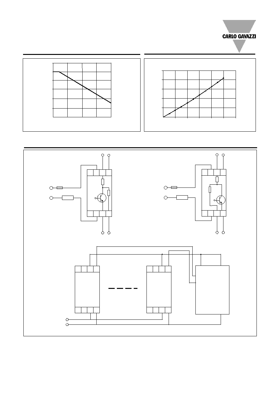
Connection Examples
~
~
LOAD
+
+
4-32VDC
0V
24 VDC
-
2T1
1L1 5A3 3A1
4A2
6A4
Alarm/Remote
3A1: Control input 4-32VDC
5A3: Alarm output PNP open
collector
6A4: Supply 24VDC
4A2: GND 0V
3A1: Control input 4-32VDC
5A3: Alarm output NPN open
collector
6A4: Supply 24VDC
4A2: GND 0V
100k
150E
150E
100k
2T1
1L1
24V GND
Alm Ctrl
24 VDC
+
_
GND
PLC
OUTPUT INPUT
OUTPUT
OUTPUT
2T1
1L1
24V GND
Alm Ctrl
*
Notes:
1. Control input (terminal A1) and 24VDC supply (terminal A3) must have common ground
2. RJCS ... and PLC should be sourced from the same 24VDC supply
3. RJCS ... PO and RJCS ...NO should not be connected to the same alarm line
4. It is recommended that up to 6 identical loads are connected in parallel.
Note: Based on 100% duty cycle

4
Specifications are subject to change without notice (27.06.2006)
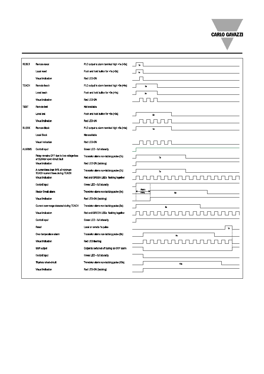
Alarm Operation
1.1 Current Setpoint
The current setpoint is the
nominal operating current
that is expected when all the
heater loads are functioning
properly. If the heater loads
are faulty or the supply volt-
age is not close to the nomi-
nal level, the wrong setpoint
will be stored.
1.2 Initialisation
When the device is shipped,
no setpoint is stored in the
flash memory. Both green
and red LEDs will flash inter-
mittently to indicate that a
setpoint must be stored
using the TEACH procedure.
1.3 Local Functions
Local functions can be acti-
vated by using the push
button on the front of the
device. While an alarm is
being issued by any SSR
connected to the common
alarm line, no local com-
mands are accepted.
1.3.1 Local TEACH
Press and hold the push but-
ton for approximately 3 sec-
onds. The red LED will flash
after each second. After the
LED flashes 3 times, release
the button. If the "teach"
command has been accept-
ed the heater loads are auto-
matically switched ON. The
red LED will flash quickly 10
times. When the current set-
point has been stored suc-
cessfully, the red and green
LEDs will scroll intermittently
to indicate that the TEACH
procedure has been com-
pleted.
It is very important to hold
the button down for only 3
flashes of the red LED to
make a successful TEACH.
If the TEACH procedure is
not successful, the device
will automatically reset to
factory default (i.e. no set-
point stored).
1.3.2 Local RESET
When an alarm has occurred
the device can be locally
RESET by pressing the push
button for 1 second. The red
LED will flash once. This will
reset the alarm. If the alarm
condition has been cleared
the device will return to nor-
mal operation. If the alarm
condition is still active, the
device will automatically go
back to alarm status.
1.3.3 Local TEST
In the absence of a signal on
the "control input" terminal,
a local TEST can be made
by pressing and holding the
button for 5 seconds. After
the red LED flashes 5 times,
release the button. The
device will switch ON the
loads for 1 second. This test
detects if there is an under-
current or heater break alarm
condition.
1.4 Remote Setup
Procedure
Remote functions can be
activated with a PLC or any
other logic controller by
applying timed pulses to the
alarm terminal: >10V for
RJCS...PO and <10V for
RJCS...NO.
1.4.1 Remote TEACH
Apply a 3 second pulse. The
red LED will flash after each
second. After the LED flash-
es 3 times and the "teach"
command has been accept-
ed, the heater loads (of all
SSRs connected to the
same alarm line) are auto-
matically switched ON and
the red LED will flash quickly
10 times. When the current
setpoint has been stored
successfully, the red and
green LEDs will scroll inter-
mittently to indicate that the
TEACH procedure has been
completed.
1.4.2 Remote RESET/
UNBLOCK
When an alarm has occurred
the device can be remotely
RESET by applying a 1 sec-
ond pulse. A 1 second pulse
will also unblock local
TEACH of all SSRs connect-
ed to the similar alarm line.
The red LED will flash once.
This will reset the alarm. If
the alarm condition has been
cleared the device will return
to normal operation. If the
alarm condition is still active,
the device will automatically
go back to alarm status.
1.4.3 Remote BLOCK
Applying a 5 second pulse
will induce the device to
block local TEACH. After
this, no local TEACH com-
mands are accepted. To
unblock this situation, a
remote RESET must be
issued. If 24V supply is
removed, local TEACH
BLOCK is lost. Another
REMOTE BLOCK should be
issued.
2 Alarms
2.1 Alarm DELAY
A potentiometer on the front
of the device allows a time
delay on the heater break
alarm between 2 and 40
seconds. For an alarm signal
to occur, the alarm condition
must persist throughout this
time period. The alarm out-
put is enabled only after this
time delay has passed.
However, if the control input
is disabled for a period of
time equal to four times the
delay setting, the internal
alarm delay count is reset
automatically.
2.2 Relay remains OFF due
to Line Voltage Loss or
Thyristor Open Circuit
Failure.
The device generates one
pulse with duration of 7 sec-
onds on the alarm terminal.
This alarm is non-latching.
The red LED remains ON
after this alarm condition
until a RESET is issued.
2.3 Heater Break.
A Heater Break alarm is
given if the current mea-
sured through the device is
13% less than the Current
Setpoint stored in the flash
memory. The device gener-
ates one pulse with duration
of 8 seconds on the alarm
terminal. The alarm signal is
non-latching. The red LED
remains ON after this alarm
condition until a RESET is
made. If the measured cur-
rent changes to within 10%
of the Current Setpoint,
before the Alarm DELAY
time has elapsed, the Alarm
DELAY timer is reset.
2.4 Over-temperature or
Over-current.
This alarm occurs if any one
of following two conditions
is true:
1. The device detects an
internal over-temperature
condition at any time during
operation and switches off
the output. The red LED
flashes intermittently.
2. A current above the nomi-
nal device rating is mea-
sured during current set-
point TEACH. This action
erases the current setpoint
from flash memory and both
red and green LEDs will flash
intermittently until a TEACH
procedure with an accept-
able current is carried out.
In both cases, the device
generates one pulse with
duration of 9 seconds on the
alarm terminal. The alarm
signal is non-latching.
2.5 Thyristor Short Circuit.
The device generates one
pulse with duration of 10
seconds on the alarm termi-
nal. The alarm signal is non-
latching.
The red LED remains ON
after this alarm condition
until a RESET is made.
2.6 Alarms Connected in
Parallel to one PLC Input
and one PLC Output.
For REMOTE operation, up
to 50 devices can be con-
nected in parallel to at least
one PLC input. This PLC
input must also be connect-
ed in parallel to the PLC out-
put. The PLC input must be
programmed to detect
alarms while the PLC output
must be programmed to
supply the pulses required
for REMOTE Setup. When
more than one device is pre-
sent, pulses from the PLC
output or alarm pulses from
any device will cause the red
LEDs on all devices in paral-
lel to flash intermittently for a
max. of 6.25 seconds. After
this time, if there is a device
in alarm condition, only the
red LED of that device will
be ON.
RJCS
Specifications are subject to change without notice (27.06.2006)
5
Example
The alarm delay is set at 2s
(min). If the full load current is
set at 30A, then there will be
an alarm condition if the cur-
rent is under 26.1A for more
than 2s. (Any fluctutation in
the load current that is pre-
sent for <2s will not be sig-
nalled ≠ this is intended to
eliminate false alarms due to
short duration under-voltage
conditions on the supply
phase). If the control input
goes off within the 2s, the
alarm timer will not be reset
provided the control input
goes on again within 8s
(4x2s).
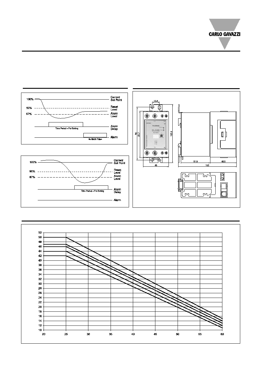
Alarm Operation
Alarm Condition
All dimensions in mm.
Reset Condition
RJCS
Dimensions
Derating vs. Spacing Curves
Surrounding temp. (∞C)
Note: Based on 100% duty cycle
22.5mm
10.0mm
6.0mm
3.0mm
0.0mm
Load Curr
ent (AACrms)
6
Specifications are subject to change without notice (27.06.2006)
Setup and Alarms
Note: Above shows pulses for PNP device