
Solid State Relay
Two-in-one(Duo)
Number of switching poles
Switching mode
Rated operational voltage
Control voltage
Rated operational current
Terminal layout
Specifications are subject to change without notice (11.07.2006)
1
∑ 2 in 1 semiconductor contactor
∑ Two control inputs - two independently switched poles
∑ Direct copper bonding (DCB) technology
∑ LED-indication for each pole
∑ Housing free of moulding mass
∑ Cage clamp output terminals
∑ Input range: 4-32 VDC
∑ Operational ratings: up to 2x45 AAC and 600 VAC
∑ Non-repetitive voltage: up to 1200 Vp
∑ Opto-isolation > 4000 VACrms
Product Description
Ordering Key
This product is designed in
such a way as to replace elec-
tro-mechanical contactors in
industrial heating and motor
applications, especially when
switching is frequent. This
product is ready to mount on
DIN-rail or chassis and comes
with integral heatsink. Cage
clamp terminals are used to
ensure secure load connection
with cable up to 25mm
2
.
The RJD2A series consists of
two switching poles which are
independently controlled.
Green LEDs indicate the sta-
tus of each control input. The
relay will switch on when the
sinosodial curve crosses zero
and switches off when the cur-
rent crosses zero.
Solid State Relays
2 Independently Switched Poles
Integrated Heatsink
Type RJD2A - Duo
Type Selection
Switching
Rated operational
Control voltage
Rated operational
mode
voltage
current
A: Zero switching
23: 230 VACrms
D: 4-32VDC
30: 2x30 AACrms (Midi)
60: 600 VACrms
45: 2x45 AACrms (Power)
RJ D 2 A 60 D 30 E
General Specifications
RJD2A23...
RJD2A60...
Operational voltage range
24 to 280 VAC
42 to 660 VAC
Non-rep. peak voltage
650 V
p
1200 V
p
Operational frequency range
45 to 65 Hz
45 to 65 Hz
Power factor
0.5 @ 230 VACrms
0.5 @ 600 VACrms
Approvals
UL, cUL
UL, cUL
CE-marking
Yes
Yes
Pollution degree
2
2
Rated operational
Control voltage
Rated operational current
voltage
2x30A (Midi)
2x45A (Power)
230VACrms
4-32VDC
RJD2A23D30E
RJD2A23D45E
600VACrms
4-32VDC
RJD2A60D30E
RJD2A60D45E
Selection Guide
MIDI
POWER
1
0
2
.
5
2
Specifications are subject to change without notice (11.07.2006)
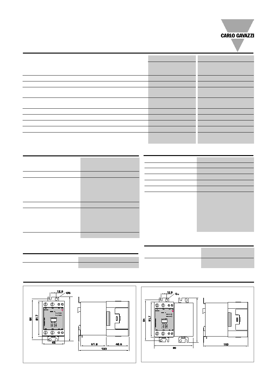
All dimensions in mm
All dimensions in mm
Dimensions
102.5
RJD2A
Output Specifications
RJD2A...30 (Midi)
RJD2A...45 (Power)
Rated operational current
AC51 @Ta=25∫C
2x30AACrms
2x45AACrms
AC53a @Ta=25∞C
2x30AACrms
2x30AACrms
Min. operational current
150 mAACrms
150 mAACrms
Rep. overload current t = 1s
< 200 AACrms
< 200 AACrms
Non rep. surge current Tj(init.)
= 25∫C and t = 10 ms
1900 Ap
1900 Ap
Off-state leakage current @
rated voltage and frequency
< 3 mArms
< 3 mArms
I
2
t for fusing t = 10 ms
18000 A
2
s
18000 A
2
s
Critical dI/dt
100 A/µs
100 A/µs
On-state voltage drop @ rated current
1.6 Vrms
1.6 Vrms
Critical dv/dt commutating
500 V/µs
500 V/µs
Critical dV/dt off-state
500 V/µs
500 V/µs
30E
23
30E
23
Weight
Approx. 480g (MIDI)
Approx. 800g (Power)
Housing material
PBT Flame Retardant
Control terminal cable size
Min
1 x 0.5 mm
2
(1 x AWG 20)
Max
1 x 4.0 mm
2
(1 x AWG 12) or
2 x 2.5 mm
2
(2 x AWG 14)
Tightening torque max.
0.6 Nm with Posidrive 0 bit
Control terminal screw
M3
Power terminal cable size
Min
1 x 4 mm
2
(1 x AWG 12)
Max
1 x 25 mm
2
(1 x AWG 3) or
2 x 10 mm
2
(2 x AWG 6)
Tightening torque max.
2.5 Nm with Posidrive 2 bit
Power terminal screw
M5
Housing Specifications
Thermal Specifications
Operating temperature
-30 to +70∫C
Storage temperature
-40 to +100∫C
Insulation
Rated insulation voltage
Input to output
4000 VACrms
Output to case
4000 VACrms
POWER
MIDI
RJD2A...30
RJD2A...45
Control voltage range
4 - 32 VDC
Pick-up voltage
3.8 VDC
Reverse voltage
32 VDC
Drop-out voltage
1 VDC
Maximum input current
15 mA
Response time pick-up
1 cycle
Response time drop-out
1 cycle
Input Specifications

Specifications are subject to change without notice (11.07.2006)
3
Derating Curve
Dissipation Curve
Load current per phase (A)
20
30
40
50
60
70
5
10
15
20
25
30
35
40
45
50
25
35
45
55
65
RJD2....45
RJD2....30
Load Current per phase (A)
T
o
tal Power Dissipation (W)
0
10
20
30
40
0
10
20
30
40
50
60
70
80
5
15
25
35
45
RJD2....30
RJD2....45
Surrounding temperature (∞C)
RJD2A
Derating vs. Spacing Curves
RJD2...30
RJD2...45
Surrounding Temp. (∞C)
22.5mm
10.0mm
6.0mm
3.0/ 0.0mm
22.5mm
10.0mm
6.0mm
3.0/ 0.0mm
Surrounding Temp. (∞C)
Load Curr
ent per Phase (A)
Load Curr
ent per Phase (A)

4
Specifications are subject to change without notice (11.07.2006)
Terminal Layout
Relay On
Connection example
RJD2A
∑ Application of DC voltage across
terminals A1-A2 will activate pole
L1-T1. The top green LED indicates
the status of the control input
across terminals A1-A2.
∑ Application of DC voltage across
terminals A3-A4 will activate pole
L2-T2. The bottom green LED indi-
cates the status of the input voltage
across terminals A3-A4.
30E
23
3
L2 A1+ A3+
1
L1
4
T2
2
T1
A2-
A4-
0V
4-32VDC
4-32VDC
0V
L1
L2
LOAD
LOAD
L3
3
L2 A1+ A3+
1
L1
4
T2
2
T1
A2-
A4-
0V
4-32VDC
4-32VDC
0V
L
L
LOAD
N N
1-Phase Loads
3-Phase Loads