Specifications are subject to change without notice (16.02.2006)
1
Rated operational Non-rep. voltage
Control current
Rated operational current
voltage
25 A
50 A
100 A
230 VAC
650 V
p
4 - 20 mA
RM1E23AA25
RM1E23AA50
RM1E23AA100
400 VAC
850 V
p
4 - 20 mA
RM1E40AA25
RM1E40AA50
RM1E40AA100
480 VAC
1200 V
p
4 - 20 mA
RM1E48AA25
RM1E48AA50
RM1E48AA100
600 VAC
1400 V
p
4 - 20 mA
RM1E60AA25
RM1E60AA50
RM1E60AA100
Switching mode
Rated operational
Rated operational
Control current
voltage
current
E: Analog switching 23: 230 VACrms* 25: 25 AACrms AA: 4 - 20 mADC
40: 400 VACrms
50: 50 AACrms
48: 480 VACrms
100: 100 AACrms
60: 600 VACrms
* For 110VACrms operational voltage, the RM1E23AA.. should be used.
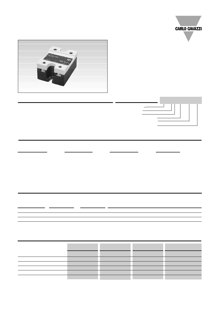
Solid State Relay
Number of Poles
Switching mode
Rated operational voltage
4 to 20 mA control current
Rated operational current
�
AC Solid State Relay
�
Analog switching (phase-angle control) for resistive
and slightly inductive load applications
�
4 to 20 mA control current
�
Rated operational current: 25, 50 and 100 AACrms
�
Rated operational voltage: Up to 600 VACrms
�
Variable intensity LED-indication according to input
current
�
Integral snubber network
Product Description
The analog switching relay works
in accordance with the phase
angle control principle, i.e., the
output switching point in the AC
sine wave depends on the control
current. 4 mA corresponds to no
switching and 20 mA corresponds
Ordering Key
Solid State Relays
to full sine wave (near linear
power response). The relay
switches off every time the
output current crosses zero,
and switches ON in accord-
ance with the applied control
current.
Type Selection
Selection Guide
General Specifications
RM 1E 23 AA ..
RM 1E 40 AA ..
RM 1E 48 AA ..
RM 1E 60 AA ..
Operational voltage range
90 to 280 VAC
340 to 460 VAC
90 to 550 VAC
410 to 660 VAC
Non-rep. peak voltage
650 V
p
850 V
p
1200 V
p
1400 V
p
Operational frequency range
45 to 65 Hz
45 to 65 Hz
45 to 65 Hz
45 to 65 Hz
Power factor
> 0.75
> 0.75
> 0.75
> 0.75
Approvals
UL, cUL, CSA
UL, cUL, CSA
UL, cUL, CSA
UL, cUL, CSA
CE-marking
Yes
Yes
Yes
Yes*
* Heatsink must be connected to ground for 600V types
Industrial, 1-Phase Analog Switching
RM 1E 60 AA 50
Type RM1E
2
Specifications are subject to change without notice (16.02.2006)
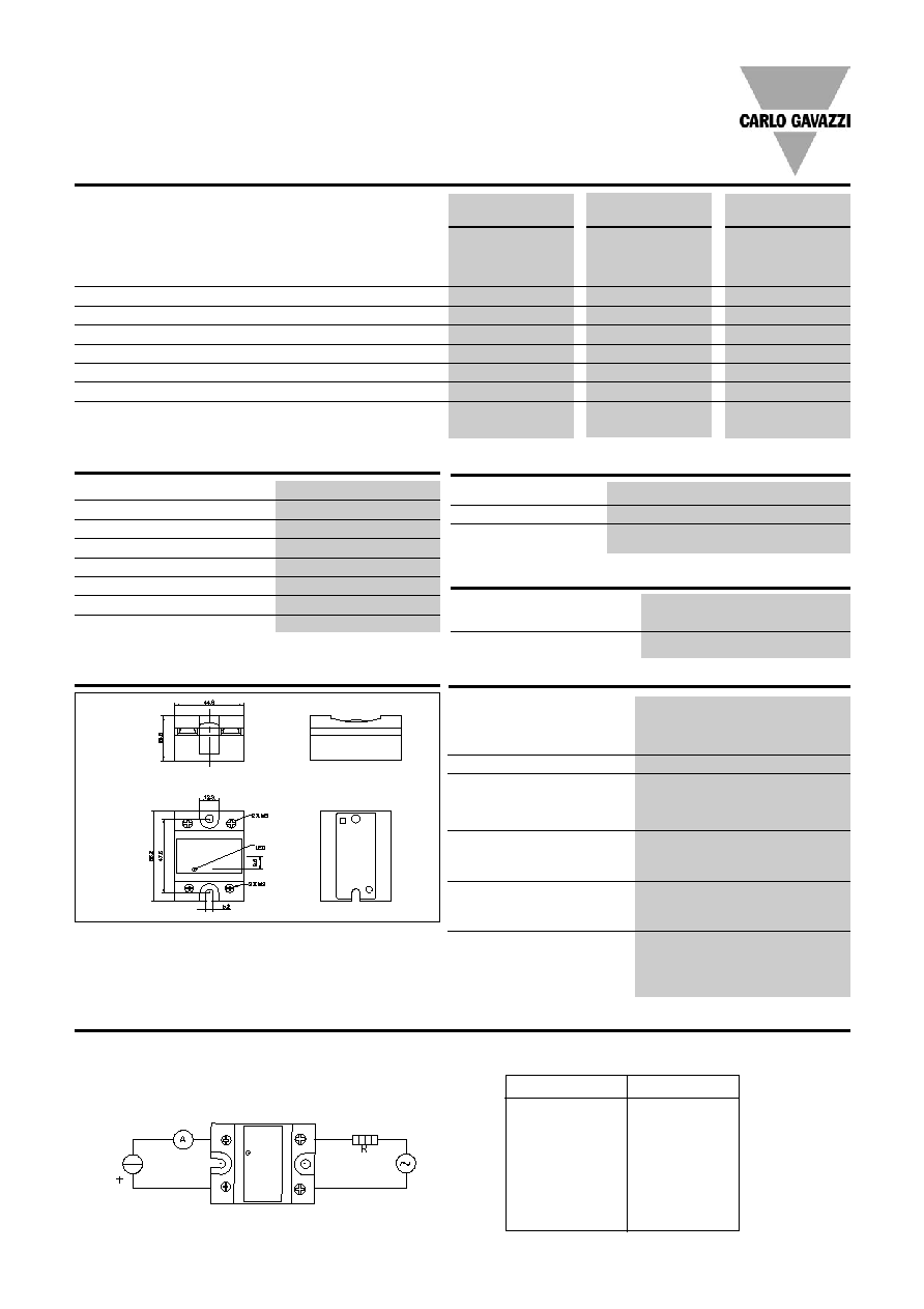
Applications
This relay is suitable for control of heaters, lighting and
slightly inductive loads such as small fans.
The relay can also be used for soft turn-on of high-power
incandescent lamps.
Transfer Characteristics
Output power as a function of control input (4 to 20mA)
I in [mA]
P out [%]
4
0
6
13
8
25
10
38
12
50
14
63
16
75
18
88
20
99
4 to
20 mA
I
in
U
line
RM1E..
A2
A1
L1
T1
RM1E..AA25
RM1E..AA50
RM1E..AA100
Rated operational current
AC51 Ta=25 �C
25 AACrms
50 AACrms
100 AACrms
AC53a Ta=25 �C
5 AACrms
15 AACrms
20 AACrms
Minimum operational current
150 mA
150 mA
150 mA
Rep. overload current t=1s
55 AACrms
125 AACrms
150 AACrms
Non-rep. surge current t=10ms
300 A
p
580 A
p
1150 A
p
Off-state leakage current
< 3 mA
< 3 mA
< 3 mA
I
2
t for fusing t= 1-10 ms
450 A
2
s
1680 A
2
s
6600 A
2
s
Critical dI/dt @ 50Hz
50 A/�s
50 A/�s
100 A/�s
Critical dV/dt off-state min.
1000 V/�s
1000 V/�s
1000 V/�s
RM1E
Input Specifications
Control current range
4-20 mADC
Pick up current
4.2 mADC
Drop out current
4.1 mADC
Response time (input to output) 20ms
Voltage drop
<10 VDC @ 20 mA
Dynamic impedance
330
Max. allowable input current
50 mA
Reverse polarity protected
Yes
The use of twisted pair cable for the control input is recommended
Output Specifications
Housing Specifications
Weight
25 A, 50 A
Approx. 60 g
100 A
Approx. 100 g
Housing material
Noryl, black
Baseplate
25 A, 50 A
Aluminium
100 A
Copper, nickel-plated
Relay
Mounting screws
M5
Mounting torque
1.5-2.0 Nm
Control terminal
Mounting screws
M3 x 9mm
Mounting torque
0.5 Nm
Power terminal
Mounting screws
M5 x 9mm
Mounting torque
2.4 Nm
Operating temperature
-20� to +70�C
(4� to +158 �F)
Storage temperature
-20� to +100�C
(-4� to +212 �F)
Junction temperature
125�C (257
�F)
Thermal Specifications
Insulation
Rated insulation voltage
Input to output
4000 Vrms
Output to case
4000 Vrms
All dimensions in mm
Dimensions
APPLY
HEATSINK
COMPOUND
Specifications are subject to change without notice (16.02.2006)
3
RM1E
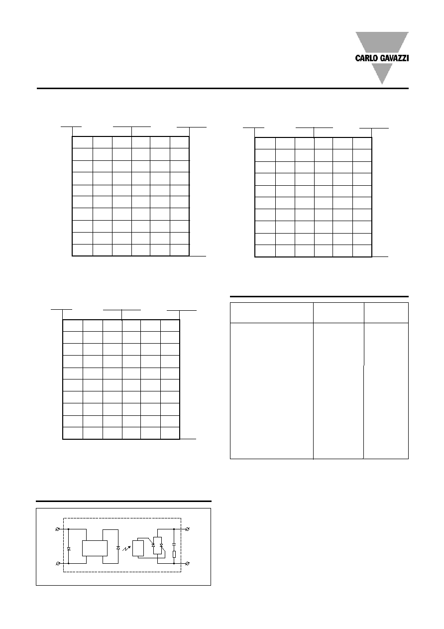
Heatsink Dimensions
(load current versus ambient temperature)
----
5.00 K/W
3.00 K/W
2.70 K/W
2.00 K/W
1.35 K/W
1.25 K/W
1.20 K/W
1.10 K/W
0.80 K/W
0.45 K/W
0.40 K/W
0.25 K/W
< 0.25 K/W
---- K/W
Carlo Gavazzi Heatsink
(see Accessories)
No heatsink required
RHS 300
RHS 100
RHS 45C
RHS 45B
RHS 90A
RHS 45C plus fan
RHS 45Bplus fan
RHS 112A
RHS 301
RHS 90A plus fan
RHS 112A plus fan
RHS 301 plus fan
Consult your distributor
Infinite heatsink
- No solution
Heatsink Selection
Thermal
resistance...
Note: For power dissipation values smaller than those
shown above, please refer to the corresponding heatsink
curve in the SSR Accessories Section is referred to.
N/A
> 0
W
> 25 W
> 55 W
> 60 W
> 60 W
> 0
W
> 0
W
> 100 W
> 80 W
> 0
W
> 0
W
> 0
W
N/A
N/A
..for power
dissipation
With the output fully ON (360
�
conduction angle)
Functional Diagram
IO
A1(+)
T1
L1
A2(-)
IC
RM1E..25
T
A
Ambient temp. [
�
C]
25.0
22.5
20.0
17.5
15.0
12.5
10.0
7.5
5.0
2.5
Power
dissipation [W]
Thermal resistance
[K/W]
Load
current [A]
3.23
2.80
2.37
1.94
1.51
1.09
23
3.70
3.21
2.73
2.24
1.75
1.26
21
4.30
3.74
3.17
2.61
2.05
1.49
18
5.07
4.41
3.76
3.10
2.44
1.78
15
6.12
5.33
4.54
3.75
2.96
2.17
13
7.58
6.61
5.64
4.66
3.69
2.72
10
9.80
8.55
7.30
6.05
4.80
3.55
8
13.5
11.80 10.09
8.37
6.66
4.94
6
-
18.3
15.7
13.04 10.39
7.74
4
-
-
-
-
-
7
2
20
30
40
50
60
70
RM1E..50
T
A
Ambient temp. [
�
C]
50.0
45.0
40.0
35.0
30.0
25.0
20.0
15.0
10.0
5.0
Power
dissipation [W]
Thermal resistance
[K/W]
Load
current [A]
1.25
1.07
0.88
0.70
0.52
0.34
55
1.46
1.25
1.04
0.84
0.63
0.42
48
1.73
1.49
1.25
1.01
0.77
0.52
41
2.08
1.80
1.51
1.23
0.94
0.66
35
2.56
2.22
1.87
1.53
1.18
0.84
29
3.24
2.81
2.38
1.95
1.52
1.09
23
4.26
3.71
3.15
2.59
2.03
1.47
18
5.99
5.22
4.45
3.67
2.90
2.12
13
9.49
8.27
7.06
5.85
4.64
3.43
8
-
17.5
15.0
12.4
9.91
7.39
4
20
30
40
50
60
70
RM1E..100
T
A
Ambient temp. [
�
C]
100.0
90.0
80.0
70.0
60.0
50.0
40.0
30.0
20.0
10.0
Power
dissipation [W]
Thermal resistance
[K/W]
Load
current [A]
0.60
0.52
0.43
0.34
0.26
0.17
117
0.74
0.64
0.54
0.44
0.34
0.24
101
0.91
0.79
0.68
0.56
0.45
0.33
87
1.09
0.96
0.82
0.68
0.55
0.41
73
1.33
1.16
1.00
0.83
0.66
0.50
60
1.66
1.45
1.24
1.04
0.83
0.62
48
2.16
1.89
1.62
1.35
1.08
0.81
37
3.01
2.64
2.26
1.88
1.51
1.13
27
4.73
4.14
3.55
2.96
2.37
1.78
17
9.94
8.70
7.45
6.21
4.97
3.73
8
20
30
40
50
60
70