 | –≠–ª–µ–∫—Ç—Ä–æ–Ω–Ω—ã–π –∫–æ–º–ø–æ–Ω–µ–Ω—Ç: RN3A22D15 | –°–∫–∞—á–∞—Ç—å:  PDF PDF  ZIP ZIP |
Specifications are subject to change without notice (30.09.2005)
1
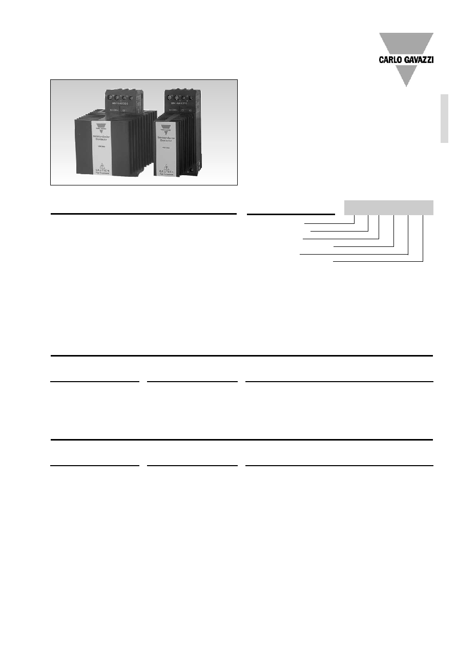
∑ Zero switching AC Solid State Relay
∑ Direct copper bonding (DCB) technology
∑ LED indication
∑ Built-in varistor
∑ Input range: 5 - 32 VDC
∑ Rated operational current: 3 x 15 and 3 x 30 AACrms
∑ Rated operational voltage: 3 x 220, 400 and 480
VACrms
∑ Non-repetitive voltage: Up to 1200 V
p
∑ Opto-insulation: > 4000 VACrms
Product Description
Ordering Key
RN 3 A 40 D 30
The SOLITRON Solid State
Contactor is designed for
industrial heating and motor
control applications. The
Solid State Contactor is
capable of switching 3-phase
loads by using only 2 switch-
ing elements for loads up to
3 x 30 AACrms AC51 load in
Star (excl. Neutral) or Delta
connections. The Solid State
Contactor is designed for
DIN-rail mounting with inte-
grated heatsink and overvolt-
age protection. The heatsink
is moved to the front for opti-
mal convection cooling in the
panel.
The contactor elements are
soldered directly to the direct
copper bonded substrate
(DCB-technology). DC con-
trol versions are availiable.
Built-in LED status indication
for applied control voltage.
Solid State Relay
Number of phases
Switching mode
Rated operational voltage
Control voltage
Rated operational current
Solid State Relays
3-Phase, 2 Pole SOLITRON
With Integrated Heatsink
Type Selection
Rated operational
Control voltage
Rated operational
voltage
current
22: 3 x 220 VACrms
D: 5 to 32 VDC
15: 15 AACrms
40: 3 x 400 VACrms
30: 30 AACrms
48: 3 x 480 VACrms
Selection Guide, 2 Pole Switching / 1-Pole direct
Rated operational
Control voltage
Rated operational current
voltage
AC51: 3 x 15 AAC
AC51: 3 x 30 AAC
AC53a: 3 x 6 AAC
AC53a: 3 x 12 AAC
22: 3 x 220 VAC rms
5-32 VDC
RN3A22D15
RN3A22D30
40: 3 x 400 VAC rms
5-32 VDC
RN3A40D15
RN3A40D30
48: 3 x 480 VAC rms
5-32 VDC
RN3A48D15
RN3A48D30
RN 3 A 40 D 30
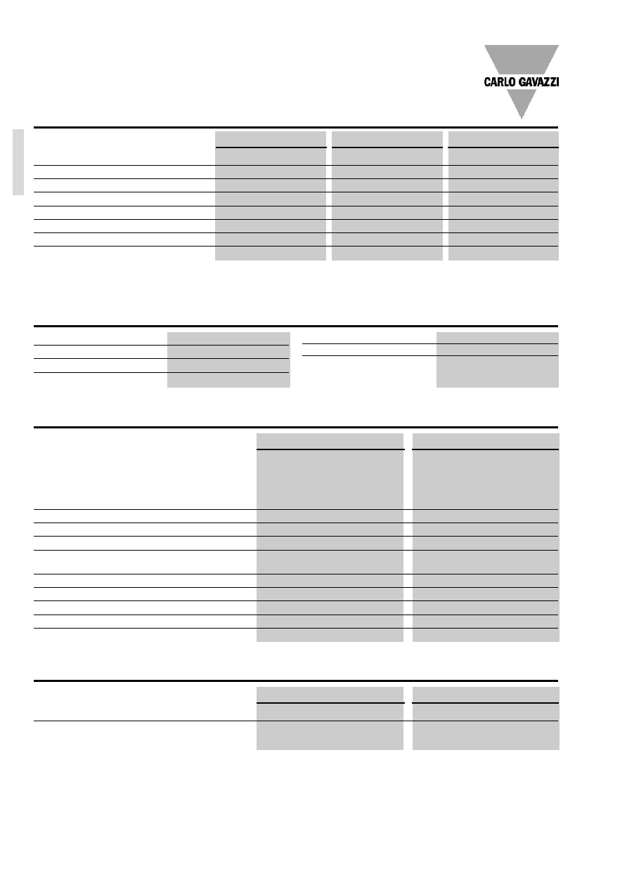
General Specifications
Input Specifications
Output Specifications
Thermal Specifications
RN 3 A
RN3A..D15
RN3A..D30
Rated operational current AC51, Ta = 30∞C
3 x 15 AACrms
3 x 30 AACrms
AC51, Ta = 40∞C
3 x 14 AACrms
3 x 27 AACrms
AC51, Ta = 50∞C
3 x 12 AACrms
3 x 24 AACrms
AC51, Ta = 60∞C
3 x 10 AACrms
3 x 18 AACrms
AC53a, Ta = 30∞C
3 x 6 AACrms
3 x 12 AACrms
Minimum operational current
200 mA
200 mA
Rep. overload current (t = 1 s)
< 55 AACrms
< 125 AACrms
Non-rep. surge current (t = 10 ms)
300 Ap
580 Ap
Off-state leakage current at
rated voltage and frequency
< 6 mA
< 6 mA
I
2
t for fusing (t = 1-10 ms)
450 A
2
s
1680 A
2
s
Critical dI/dt
50 A/µs
50 A/µs
On-state voltage drop at rated current
< 1.6 Vrms
< 1.6 Vrms
Critical dV/dt
500 V/µs
500 V/µs
Zero crossing detection
Yes
Yes
RN3A..D15
RN3A..D30
Operating temperature range
-20∞ to + 70∞C (-4∞ to + 158∞F)
-20∞ to + 70∞C (-4∞ to + 158∞F)
Storage temperature range
-40∞ to + 100∞C (-40∞ to + 212∞F)
-40∞ to + 100∞C (-40∞ to + 212∞F)
RN 3 A 40 D 30
RN3A22...
RN3A40...
R3A48...
Operational voltage range
24 - 265 VAC
42 - 440 VAC
42 - 530 VAC
Non-rep. peak voltage
650 V
p
800 V
p
1200 V
p
Varistor voltage
275 VAC
420 VAC
510 VAC
Zero voltage turn-on
< 20 V
< 20 V
< 20 V
Operational frequency range
45 - 65 Hz
45- 65 Hz
45 - 65 Hz
Power factor
> 0.5
> 0.5
> 0.5
Approvals
UL, cUL, CSA
UL, cUL, CSA
UL, cUL, CSA
CE-marking
Yes
Yes
Yes
Norms fulfilled
EN 60947-1
Low-voltage switchgear and control gear. Part 1- General Rules
EN 61000-6-2
Generic Immunity Standard. Industrial Environment
Control voltage range
5-32 VDC
Pick-up voltage
4.5 VDC
Drop-out voltage
1 VDC
Input current @ 24 VDC
< 10 mA
Response time pick-up
< 10 ms
Response time drop-out
< 20 ms
Green LED indication
Yes
2
Specifications are subject to change without notice (30.09.2005)
Specifications are subject to change without notice (30.09.2005)
3
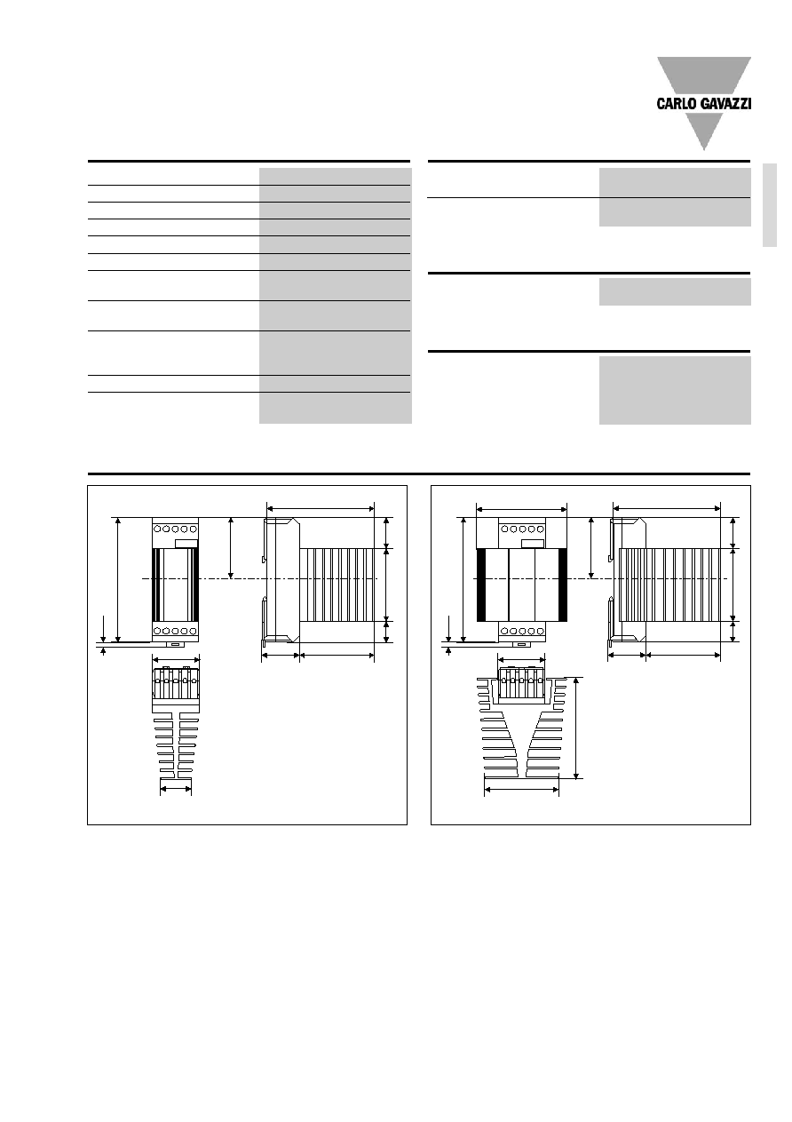
Insulation
Rated insulation voltage
input to output
4000 VACrms
Rated insulation voltage
output to case
4000 VACrms
Dimensions
Dimensions
(H x W x D)
RN..15
120 x 45 x 110 mm
RN..30
120 x 90 x 110 mm
Housing Specifications
Mounting
DIN - rail 35 mm
Weight with RHN1
470 g
Weight with RHN2
780 g
Housing material
Noryl SEI, GFN1, Black
LED window material
PC Lexan 141 R
Base plate
Aluminium, nickel plated
Potting compound
Polyurethane,
Casco Nobel
Terminals
Screw with captive wire
clamp
Power and control terminals
4 mm
2
or 2 x 2.5 mm
2
AWG12 or 2 X AWG 14
Min. 0.5 mm
2
, AWG 20
Mounting torque max.
0.6 Nm
Heatsink compound used
Electrolube HTS
Environment Specifications
Humidity max.
95%, no condensation
RN 3 A
Dimensions
4
120
45
33,7
103
71,6
37
30
20
70
60
4
120
93
72
45
89
103
71,6
37
20
70
30
60
Note: all dimensions in mm
RN 3 A 40 D 30
Note: all dimensions in mm
RN..15
RN..30
4
Specifications are subject to change without notice (30.09.2005)
RN 3 A
Applications
L
1
L
3
L
2
T
1
T
2
T
3
A
2
A
1
A
2
L
1
L
2
L
3
+A
1
1
6
4
2
5
3
Economic switching of inductive and resistive Loads
3-phase 2 pole switching allows a very economical handling of heavy loads which
have to be run in a 3-phase configuration either as a star connection or a delta
connection of the loads. With 2-pole switching and the integration of a contactor
instead of switching all 3-phases a substancial space and cost saving in the panel
can be achieved as one third of the heatsinks can be taken out and also the ven-
tilation of the panel can be reduced.
3-Phase, 2 pole Switching Principle
With SOLITRON RN.3.A.. 3-phase Relays switching with 2-poles and the integra-
tion of a contactor the electric configuration is splitted into a safety part and a
control part. In the safety part the isolation of the lkoad from the mains is assured
by a small contactor mounted in series with the Solid State Relay. The contactor
can be a very economical type as the switching is done by the Solid State Relay.
As the contactors are already switched, when the Solid State Relay is in control
of the power, no burning of the contacts will occur.
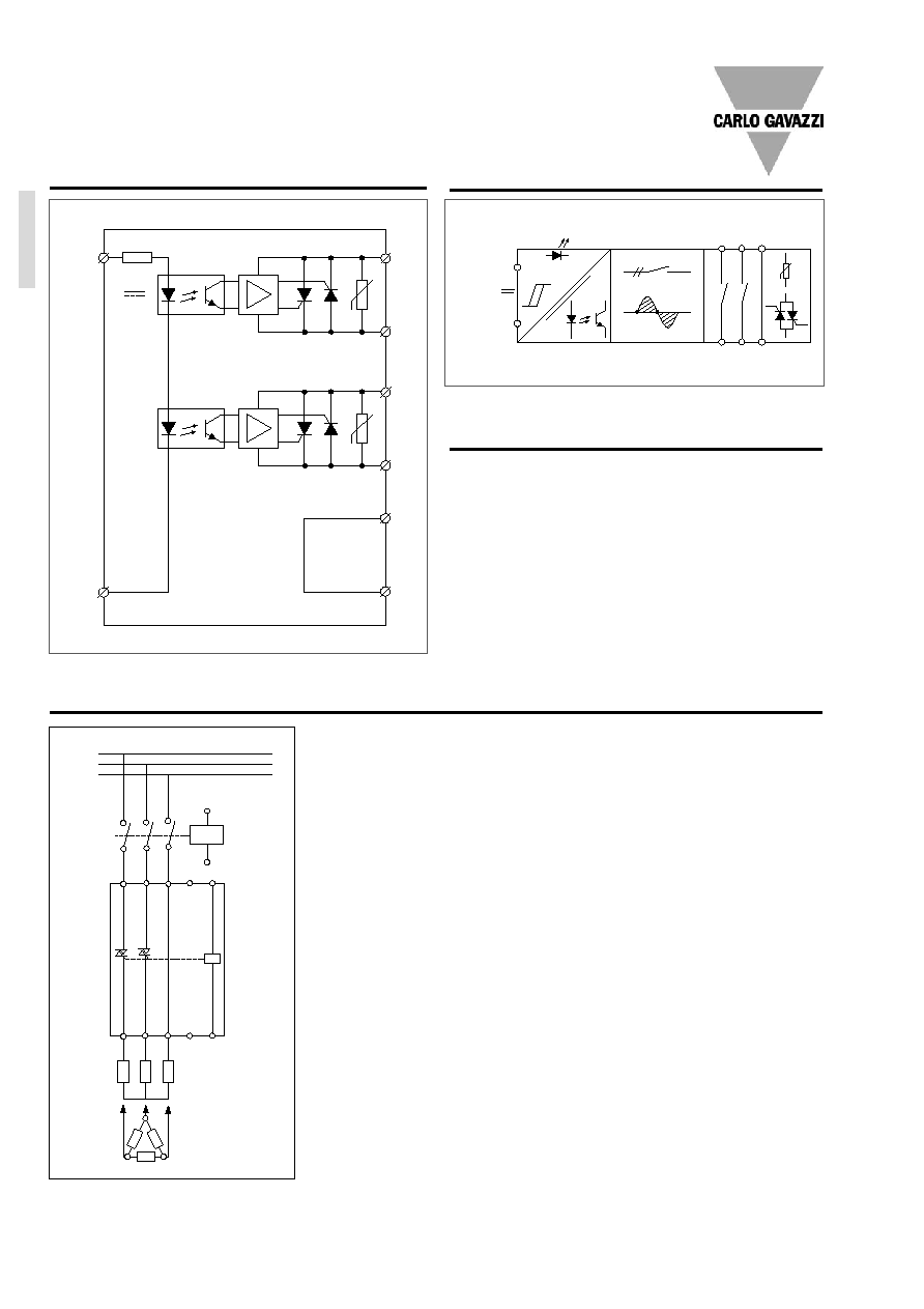
Wiring Diagram
3-phase, 2-pole RN...
Functional Diagram
3-phase, 2-pole RN...
+A
1
-A
2
Control
input
L
1
T
3
L
3
T
2
L
2
T
1
Control
input
+A
1
-A
2
L
1
L
2
L
3
T
1
T
2
T
3
Fuses
For further information refer to "General Accessories".
Star Connection
Delta Connection
Safety
part
Control
part
RN 3 A 40 D 30
L
1
L
3
L
2
T
1
T
2
T
3
A
2
A
1
A
2
L
1
L
2
L
3
+A
1
1
6
4
2
5
3
RN... trif·sico, bipolar
RN... trif·sico, bipolar
+A
1
-A
2
Control
input
L
1
T
3
L
3
T
2
L
2
T
1
Control
input
+A
1
-A
2
L
1
L
2
L
3
T
1
T
2
T
3
Star connection
Delta connection
Safety part
Control
part
Control
input
Control
input
Accessories