Specifications are subject to change without notice
(30.06.1999)
1
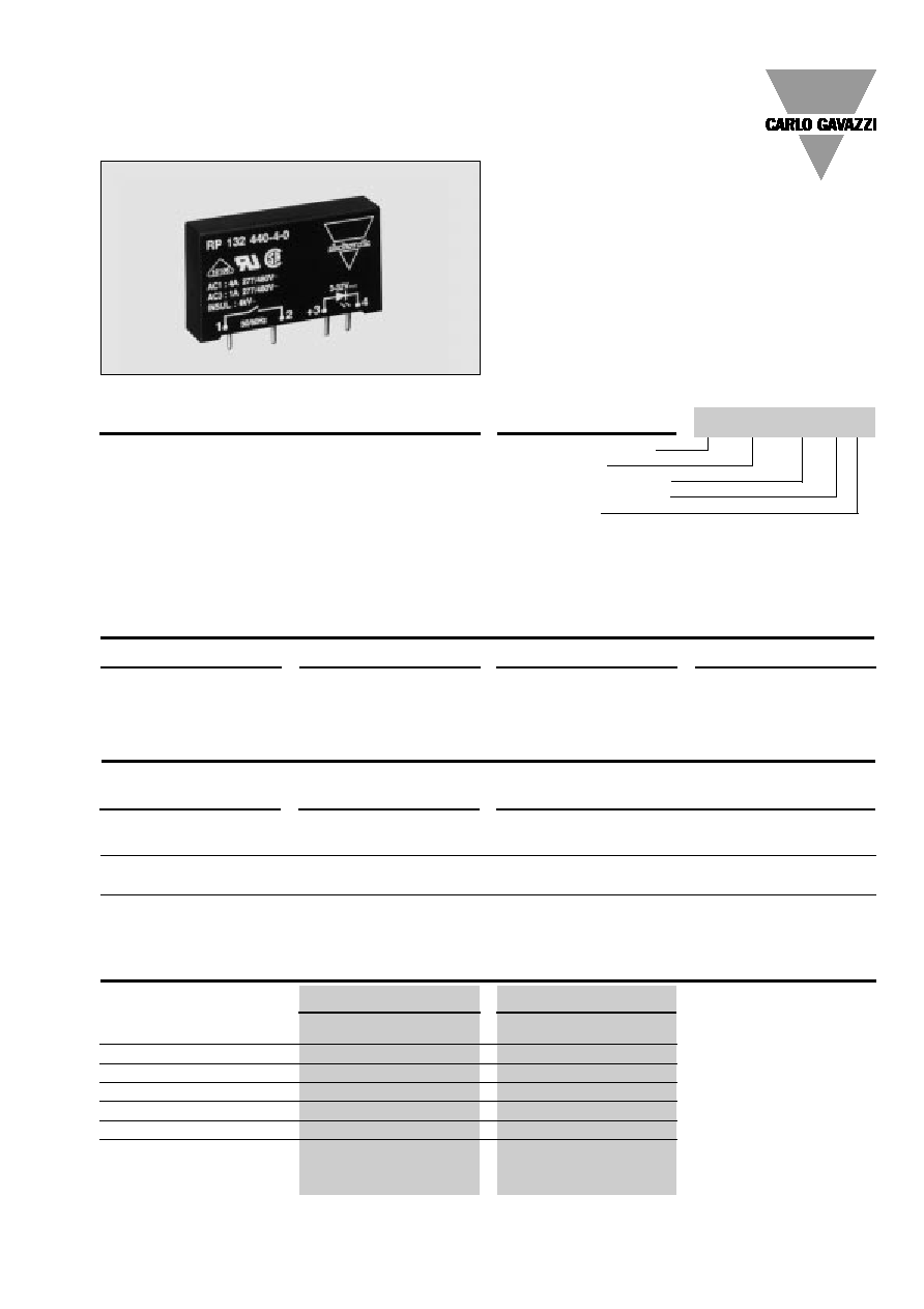
Solid State Relays
PCB, 1-Phase ZS/IO
Type RP 130 ...-.-., RP 132 ...-.-.
∑ AC Solid State Relay for PCB mounting
∑ Zero or instant-on switching
∑ Rated operational current: 2 and 4 AAC
∑ Non-repetitive voltage: Up to 850 Vp
∑ Rated operational voltage range: Up to 400 VACrms
∑ Input range: 3 to 32 VDC
∑ Insulation: OPTO (input-output) 4000 VACrms
Product Description
Solid State Relay (PCB)
Switching mode
Rated operational voltage
Rated operational current
Control voltage
Ordering Key
Type Selection
Switching mode
Rated operational voltage
Rated operational current
Control voltage
130: Zero switching
240: 230 VACrms
2: 2 AACrms
0: 3 to 32 VDC
132: Instant-on switching
440: 400 VACrms
4: 4 AACrms
Selection Guide
Rated operational voltage
Control voltage
Rated operational current
2 AACrms
4 AACrms
230 VACrms
3 to 32 VDC
RP 130 240-2-0*
RP 130 240-4-0*
RP 132 240-2-0**
RP 132 240-4-0**
400 VACrms
3 to 32 VDC
RP 130 440-2-0*
RP 130 440-4-0*
RP 132 440-2-0**
RP 132 440-4-0**
* Zero switching
** Instant-on switching
General Specifications
RP 13. 240-.-0
RP 13. 440-.-0
Operational voltage range
24 to 280 VACrms
48 to 480 VACrms
Non-rep. peak voltage
650 V
p
850 V
p
Zero voltage turn-on
20 V
40 V
Operational frequency range
45 to 65 Hz
45 to 65 Hz
Power factor
0.5 @ 230 VACrms
0.5 @ 400 VACrms
Approvals
UL, CSA, VDE
UL, CSA, VDE
CE-marking
Yes
Yes
RP 130 240-4-0
The zero switching relay for
PCB mounting is used for a
wide range of applications
with either resistive or induc-
tive loads.
The zero switching relay swit-
ches on when the AC sine
curve just crosses the zero
value, and the relay switches
off when the current crosses
zero.
The instant-on switching
relay switches on immediate-
ly when the control voltage is
applied. The relay switches
off when the current crosses
the zero value.
2
Specifications are subject to change without notice
(30.06.1999)
Weight
Approx. 10 g
Housing material
Noryl GFN 1, black
Terminals
Copper, tin-plated
Potting compound
Flame retardant polyurethane
Housing Specifications
Accessories
Fuses and varistors:
For further information refer to "General Accessories".
RP 130 .40-.-0
RP 132 .40-.-0
Control voltage range
3 to 32 VDC
3 to 32 VDC
Pick-up voltage
3 VDC
3 VDC
Drop-out voltage
1 VDC
1 VDC
Reverse voltage
6 VDC
6 VDC
Response time pick-up
1/2 cycle
1 ms
Response time drop-out
1/2 cycle
1/2 cycle
Input impedance
1.5 k
1.5 k
Input Specifications
Output Specifications
RP 13. .40-2-0
RP 13. .40-4-0
Rated operational current AC 1
2 Arms
4 Arms
AC 3
2 Arms
3 Arms
Minimum operational current
20 mArms
20 mArms
Rep. overload current t=1 s
6 A
p
12 A
p
Non-rep. surge current t=20 ms
42 A
p
90 A
p
Off-state leakage current
@ rated voltage and frequency
5 mArms
5 mArms
I
2
t for fusing t=1-10 ms
9 A
2
s
40 A
2
s
Critical dl/dt
10 A/µs
10 A/µs
On-state voltage drop
@ rated current
1.6 Vrms
1.6 Vrms
Critical dV/dt commutating
4 V/µs
4 V/µs
Critical dV/dt off-state
100 V/µs
100 V/µs
RP 130 ...-.-., RP 132 ...-.-.
Thermal Specifications
RP 13. .40-2-0
RP 13. .40-4-0
Operating temperature
-20∞ to +70∞C (-4∞ to +158∞F)
-20∞ to +70∞C (-4∞ to +158∞F)
Storage temperature
-40∞ to +100∞C (-40∞ to +212∞F)
-40∞ to +100∞C (-40∞ to +212∞F)
Junction temperature
125∞C (
257∞F)
125∞C (
257∞F)
R
th
junction to case
20.5 K/W
15.6 K/W
R
th
junction to ambient
37.5 K/W
22.5 K/W
Insulation Input-Output
Rated insulation voltage
4000 VACrms
Insulation resistance
10
10
Insulation capacitance
8 pF
Reference voltage
according to VDE 01 10 B
Insulation group C
500 VACrms, 600 VDC
Applications
These relays can be used to
switch heaters, motors, lights,
valves or solenoids.
When used at full load cur-
rent, the relays must be placed
vertically. If more than one
relay is mounted, please al-
low a minimum distance of 20
mm in between for sufficient
air cooling.
Specifications are subject to change without notice
(30.06.1999)
3
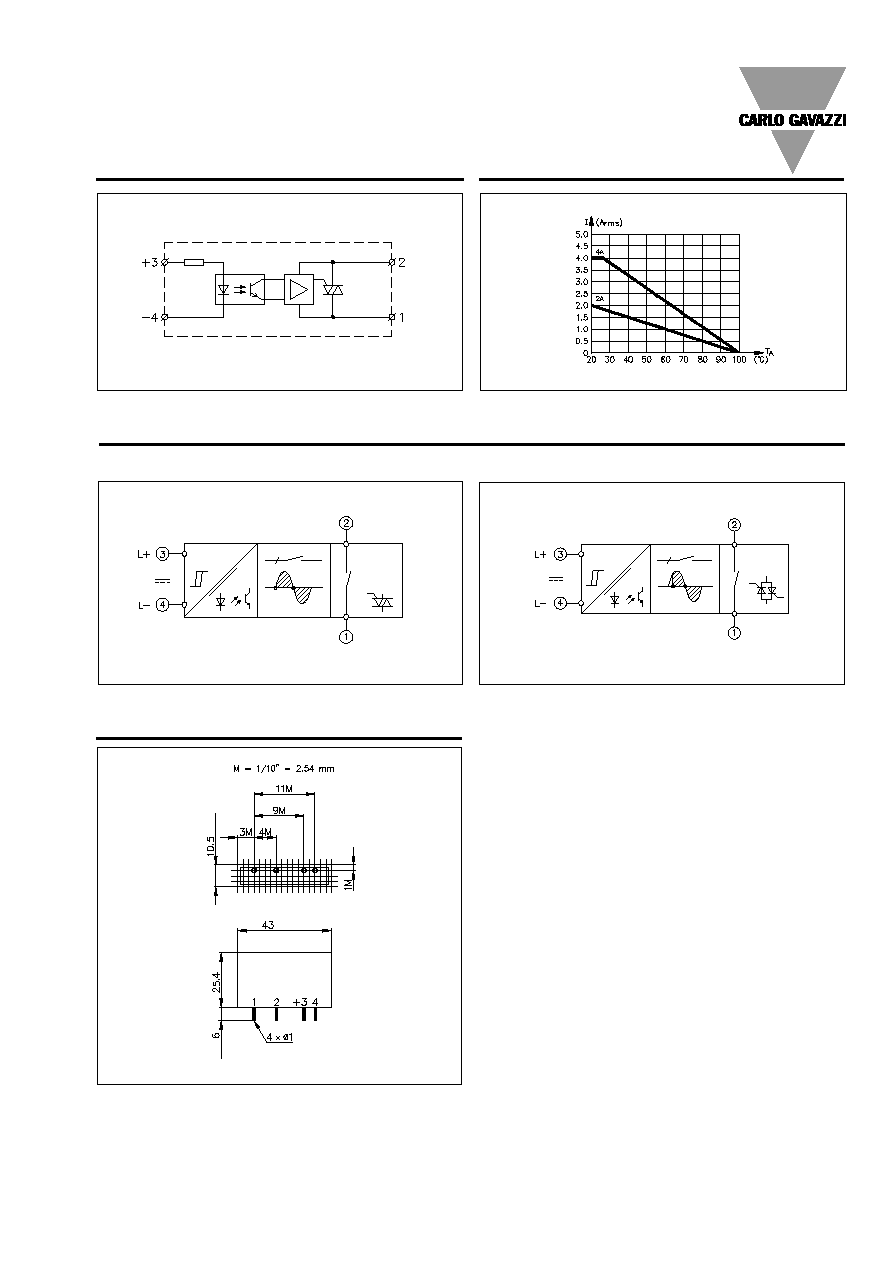
Derating Curve
Line/load
Control
input
RP 130 .40-.-0
Functional Diagrams
RP 132 .40-.-0
Dimensions
Wiring Diagram
RP 130 ...-.-., RP 132 ...-.-.
* = ± 0.2 mm
** = ± 0.5 mm
Rated operational current
Ambient temperature
Control
input
Mains input/load output
Load output/mains input
Control
input
Mains input/load output
Load output/mains input
**
*
*
**