
Specifications are subject to change without notice
1
Application
Rated operational
Rated operational
Remote-On input
voltage
current
A: 1-phase transformer
1: 110 VAC (90-135 VAC)
1: < 16 A
1: 4-32 VDC
2: 230 VAC (160-270 VAC)
2: > 16 A (with ext.
3: 400 VAC (280-440 VAC)
thyristor module)
4: 500 VAC (350-550 VAC)
Transformer soft starter
Application
Rated operational voltage
Rated operational current
Remote-On input
Output signal
Detection mains voltage deformation
Special version
Ordering Key
Transformer Switching
Transformer Soft Starter
Type TSE6-1A.......
Product Description
The transformer soft starter
TSE6-1 is an electronic relay
with a new integrated soft
start procedure which
switches on single phase
transformers without inrush
current. It can either be
transformer with EI-cut strip-
wound core or toroidal core
with any secondary load or it
can be a parallel connection
of different types of trans-
formers. The soft start pro-
cedure used is patented and
works with the premagnet-
isation of the transformer.
The TSE6-1 is available in
three different versions: As
compact version up to 16 A
with internal thyristor and
bypass relay or as control
unit in combination with ex-
ternal thyristors or semicon-
ductor relay with bypass
contactor for high currents
(> 16 A).
Type Selection
Rated operational voltage
Rated operational
Rated operational
current < 16 A
current > 16 A
(with ext. thyristor module)
110 VAC (45-65 Hz)
TSE 6-1A1113100
TSE 6-1A1213100
230 VAC (45-65 Hz)
TSE 6-1A2113100
TSE 6-1A2213100
400 VAC (45-65 Hz)
TSE 6-1A3113100
TSE 6-1A3213100
500 VAC (45-65 Hz)
TSE 6-1A4113100
TSE 6-1A4213100
Selection Guide
� Soft starting/switching of 1-phase
transformers
� Rated operational voltage: up to 500 VAC, 50/60 Hz
� Rated operational current: up to 63 A
� LED-indication for operation and alarm
TSE6-1A3213100
2
Specifications are subject to change without notice
TSE6-1A .......
General Specifications
Mode of Operation
The TSE6-1 is used for soft-
starting of 1-phase trans-
formers. The factory is deli-
vering the TSE6-1 calibrated
for transformers with EI, MI-,
resp. UI-cores. The adap-
tation for other transformer ty-
pes is possible by adjusting
the build-in selector. The
TSE6-1 can be controlled eit-
her with a direct voltage, com-
parable to a solid state relay
or in another version with a
volt-free contact. The signal
output (Hi, Lo) is conductive
as soon as the TSE6-1 has
fully switched on after the
premagnetisation of the trans-
former. A green LED is indica-
ting the status of the signal
output. With the bypass relay
resp. contactor the control
unit is short-circuited directly
after switching on to avoid
energy loss. When using thyri-
stors or semiconductor relays
with heatsink the bypass relay
resp. contactor is not needed.
The TSE6-1 recognizes itself
whether a bypass contactor is
connected or not.
The TSE6-1 controls the main
voltage and turns off if the vol-
tage limiting values are exceed-
ed. The red LED blinks with a
frequency of 1 Hz in case of
undervoltage and with 4 Hz
frequency in case of overvol-
tage. If there is an internal fault
the red LED is continuously
on.
An internal jumper (J1) is cali-
brating whether the TSE6-1 is
switching on itself after a fault
(default position) or if it has to
be returned by taking away
the mains voltage or the re-
mote-On signal.
As an option the TSE6-1 has
the possibility of reacting to
mains voltage deformations
(loop failures, short power fai-
lures) which cause saturation
current in the transformer, re-
leasing the fuse of the trans-
former by turning off the
TSE6-1 and the transformer
before the saturation currents
occur and then directly swit-
ching on again the transfor-
mer with the standard soft-
start procedure.
Type of construction
Encapsulated, Euronorm
housing
Environment
Degree of protection
IP 20
Pollution degree
2 (IEC 60664)
Ambient temperature
0� to +50�C (32� to -122�F)
Protection against surges
Type B-circuit breaker for
rated operational current.
When using a mismatched
or oversized circuit breaker
regarding speed and sizing
the TSE6-1 can be damaged
by means of overload or
short-circuit
Pick-up time
Approx. 0.3 (El-core) - 1.8 s
(Toroid core) after mains-On
Approx. 0.1 (El-core) - 0.5 s
(Toroid core) with remote-On
In special cases 0.02 - 0.04 s
remote-On is possible
Max. switching rate
Not limited
Remote-On input
4 - 32 V (DC)
U
max
= �40 V,
I
min
= 1 mA (by 4 V),
I
max
= 12 mA (by 32 V).
The input is galvanically
separated by means of opto-
coupler. Selection of remote-
On/remote Off via internal
jumper (factory set jumper
position is "remote-On").
Output signal
Open-Col.-output, potential-
free
I
max
= 50 mA, U
max
= 70 V
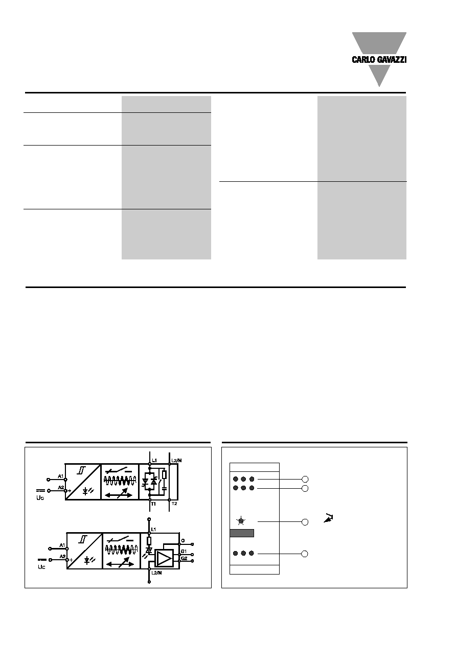
Functional Diagrams
Operation Diagram
1
2
3
4
L1
A1 A2
L2/N Lo
Hi
3
2
1
5
4
G1
0
G2
Transformer Selection
CW: 5 ms @ 50 Hz
CCW: 1 ms @ 50 Hz
Set-points:
� Transformers EI/UI/MI 3-4 ms
� Variac
3 ms
� Toroid Transformer
2 ms
On-Signal 70V/50 mA
(Full on message)
Output for bypass contactor (L1)
TSE6-1A3113100
TSE6-1A3213100
Specifications are subject to change without notice
3
Housing Specifications
Dimensions
Weight
270 g
Housing material
PC/ABS Blend
Colour
grey
Terminal block
PBTP
Colour
black
Bottom clip
POM
Colour
black
Diode cover
PC
Colour
black transparent
Front knob
PC
Colour
black
Terminals
Screw terminals
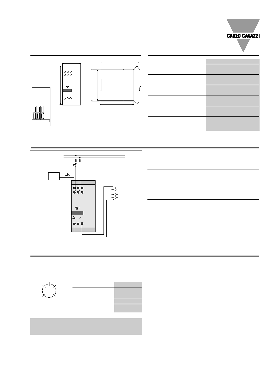
Wiring Diagram
�
A main switch is not required when using the remote-
On input for switching on/off.
�
F1, F2 are fast fuses for operational current or circuit
breakers with B characteristic.
�
F2 can be eliminated when TSE6-1 is connected to L1
and N.
LED fault indication (red)
Blinks with 1 Hz frequency when voltage too low
Blinks with 4 Hz frequency when voltage too high
Continuous output when internal fault
LED switched ON (green)
Flashing when transformer switched on
T S E 6 - 1 A 3 1 1 3 1 0 0
A l a r m O n
T r a n s f o r m e r
S e l e c t i o n
L 1
A 1 A 2
L 2 / N L o
H i
3
2
1
5
4
T 1
T 2
P o w e r
s u p p l y
L 1
L 2 / N
F 1
S 1
S 2
H i
L o
F 2
TSE6-1A .......
45
91.7
102
82
86.3
78
All dimensions in mm
Tuning
Type of transformer
Position
Transformer
(EI-, UI-MI-core)
3-4
Variac
3
Toroid transformer
2
Caution:
The TSE6-1 contains thyristors. When TSE6-1
is turned off there is no galvanic separation
between transformer and mains supply.
Jumper J1
(inside, on PCB)
When jumper J1 is closed,
TSE6-1 switches ON auto-
matically after a fault (high-/
low-voltage, technical fault).
When jumper J1 is open,
TSE6-1 switches ON only
when remote-ON resp. mains
is switched OFF and ON
again.
Default setting: jumper J1
closed.
Jumper J2
(inside, on PCB)
When jumper J2 is closed,
TSE6-1 switches ON without
remote-ON signal. When
jumper J2 is open, TSE6-1
switches ON only when re-
mote-ON signal is ON.
The size of pre-magnetisation of the transformer can be ad-
justed by the tuning knob
named transformer selection.
Transformer Selection
3
2
1
5
4
CCW
CW
CW: T/4 (5 ms at 50 Hz)
CCW: T/20 (1 ms at 50 Hz)
4
Specifications are subject to change without notice
Thermal Specifications RTH .
The turn on is made by opto-triacs (Sitac) via a resistor
(160
) from the anode side of the thyristor.
Max. gate current
I
GT
=
220 mA
Max. perm. delay on turn on
t
gd
=
200 �s
Max. perm. reset time
t
q
=
250 �s
Gate-cathode resistor
R
GK
=
120
/0,25 W
Gate-cathode diode
D
GK
= z.B.
IN4007
Operational voltage range
42 to 530 VAC
Non-rep. peak voltage
1200 V
p
Varistor voltage
510 VAC
Operational frequency range
45 to 65 Hz
Power factor at rated voltage
0.5
CE-marking
Yes
External Thyristor-Modules RTH .
When current > 16 A the
TSE6-1 must be used in
combination with one of the
three thyristor modules
RTH1, RTH2 or RTH3. In
these thyristor modules
gate-cathode diodes (e.g.
1N4007), gate-cathode-re-
sistor and the RC-part (47
/
150 nF) are already integrat-
ed. For this reason these
thyristor modules can be
connected to the TSE6-1
without any restrictions.
Correctly dimensioned heat-
sinks are already integrated
in the thyristor-modules.
General Specifications RTH .
TSE6-1A .......
RTH1
RTH2
RTH3
Operational temperature
-20� to +70�C (-4� to +158�F)
-20� to +70�C (-4� to +158�F)
-20� to +70�C (-4� to +158�F)
Storage temperature
-20� to +70�C (-4� to +158�F)
-20� to +70�C (-4� to +158�F)
-20� to +70�C (-4� to +158�F)
Junction temperature
< 125�C (257�F)
< 125�C (257�F)
< 125�C (257�F)
R
th
juntion to ambient (AC load)
2.8 K/W
2.8 K/W
2.8 K/W
Output Specifications RTH .
RTH1
RTH2
RTH3
Rated operational current
AC 1 @ Ta = 30�C
30 A
50 A
63 A
@ Ta = 40�C
25 A
50 A
60 A
@ Ta = 50�C
23 A
38 A
55 A
@ Ta = 60�C
20 A
30 A
50 A
AC 3 @ Ta = 60�C
6 A
12 A
24 A
Min. operational current
200 mA
200 mA
200 mA
Rep. overload current t = 1 s
(Tj = 25�C)
55 A
125 A
150 A
Non-rep. surge current t = 10 ms
(Tj = 25�C)
250 A
p
600 A
p
1000 A
p
Off-state leakage current
@ rated voltage and frequency
(Tj = 125�C, max.)
< 1 mA
< 1 mA
< 1 mA
I
2
t for fusing
t = 1 to 10 ms
310 A
2
s
1800 A
2
s
5000 A
2
s
Critical dV/dt
500 V/�s
500 V/�s
500 V/�s
Specifications are subject to change without notice
5
Housing Specifications RTH .
Insulations RTH .
Environment Specifications RTH .
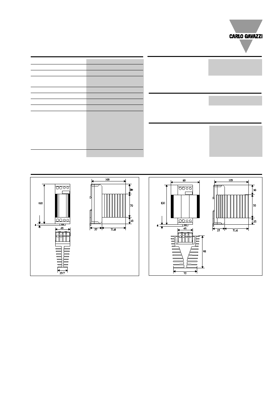
Dimensions RTH .
Rated impulse withstand volt.
Input to output
4000 V
rms
Output to heatsink
4000 V
rms
Humidity max.
95%, no condensation
Dimensions (H x W x D)
RTH1
120 x 45 x 110 mm
RTH2, RTH3
120 x 90 x 110 mm
Mounting
DIN-rail 35 mm
Weight RTH1
450 g
Weight RTH, RTH3
750 g
Housing material
Glass reinforced noryl
SE1FGFN1
LED-window material
PC Lexan 141 R
Base plate
Aluminium, nickel plated
Potting compound
Polyurethan, casco nobel
Terminals
Screw with captive wire clamp
Control terminals nominal
4 mm
2
or 2 x 2.5 mm
2
AWG 12 or 2 x AWG 14
Min.
0.5 mm
2
, AWG 20
Mounting torque max.
0.6 Nm
Power terminals nominal
10 mm
2
or 2 x 6 mm
2
AWG 6 or 2 AWG 10
Min.
1 mm
2
,
AWG 16
Mounting torque max.
2.0 Nm
Heatsink compound used
Dow Corning 340
TSE6-1A .......
Dimensions RTH .
RTH1
RTH2, RTH3
All dimensions in mm
All dimensions in mm
6
Specifications are subject to change without notice
TSE6-1A .......
RTH2, RTH3
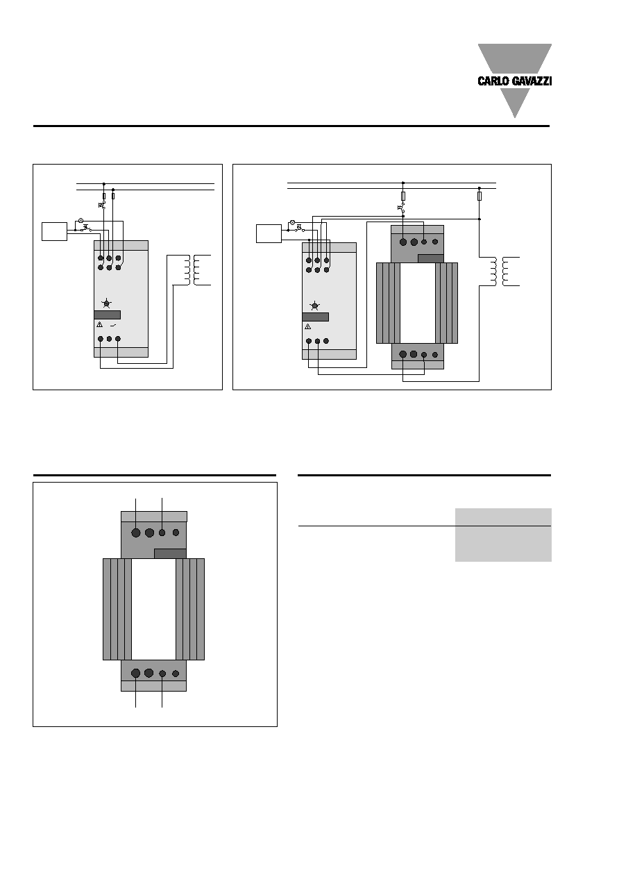
Connections RTH .
Wiring Examples
TSE6-1A .1 soft starter in combination with external thyristor module
for transformers with load > 16 A.
TSE6-1A .2 soft starter for transformers
with any load.
� Switch ON/OFF with S1 and/or S2 via re-
mote-ON input.
� F2 is not required, when TSE6-1 is con-
nected to L1 and N.
� Switch ON/OFF with S1 and/or S2 via remote-ON input.
� F2 is not required, when TSE6-1 is connected to L1 and N.
� Bypass contactor not required when thyristor-module with heatsink is
used.
T S E 6 - 1 A 3 1 1 3 1 0 0
A l a r m O n
T r a n s f o r m e r
S e l e c t i o n
L 1
A 1 A 2
L 2 / N L o
H i
3
2
1
5
4
T 1
T 2
P o w e r
s u p p l y
L 1
L 2 / N
F 1
S 1
S 2
H i
L o
F 2
P o w e r
s u p p l y
L 1
L 2 / N
S 1
F 1
F 2
H i
S 2
L o
T S E 6 - 1 A 3 2 1 3 1 0 0
A l a r m O n
T r a n s f o r m e r
S e l e c t i o n
L 1
A 1 A 2
L 2 / N L o
H i
3
2
1
5
4
G 1
0
G 2
R T H .
G 2
T 1
G 1
L 1
TSE6-1 detects automatically if a bypass contactor is connec-
ted.
Peak load of contacts (AC1)
I
kac1
= I
load
Coil voltage
When TSE6-1 working with U
L1N
U
BSSP
= U
L1N
When TSE6-1 working with U
L1L2
U
BSSP
= U
L1L2
or U
L1N
*)
Only used with external thyristor-module or with SSR
Bypass-Contactor
*)
L1
G1
T1
G2
RTH.