Specifications are subject to change without notice (25.10.99)
1
Plug
Output
Time range
Supply: 9-29 VDC
Circular
2 x SPDT
Start attempts: 1.5 to 30 s
Pause: 3 to 60 s
S 109 256 712
Timers
Housing
Type/function
Output
Power supply
Time ranges
Duration of start attempts, T1
1.5 to 30 s
Duration of pause, T2
3 to 60 s
Time range accuracy
0 to +10% max.
min. actual time
min.
set time
Repeatibility devation
1%
Time variation
Within rated power supply
0.1%/V
and ambient temperature
0.2%/∞C
Reset
Power supply interruption min.
Time and/or relay
100 ms
Power supply DC types
Installation cat. III (IEC 60664)
Rated operational voltage
through pins 2 & 10
712
12 to 24 VDC -25/+21%
(pin 2 pos.)
Rated insulation voltage
None
Rated transient protection volt. 800 kV (1.2/50 µs)
Consumption
125 mA
Output
2 x SPDT
Basic electrical insulation
250 VAC (rms) (contact/
elec., contact/contact)
Contact ratings(AgCdO)
µ (micro gap)
Resistive loads
AC 1
10 A/250 VAC (2500 VA)
DC 1
1 A/250 VDC (250 W)
or
10 A/25 VDC (250 W)
Smal inductive loads
AC 15
2.5 A/230 VAC
DC 13
5 A/24 VDC
Mechanical life
30 x 10
6
operations
Electrical life
AC1
2.5 x 10
5
operations
(at max. load)
Operating frequency
7200 operations/h
Insulation voltages
Rated insulation voltage
2.0 kVAC (rms) (cont./elec.)
Rated transient protection volt.
4 kV (1.2/50 µs) (cont./elec.)
(IEC 60664)
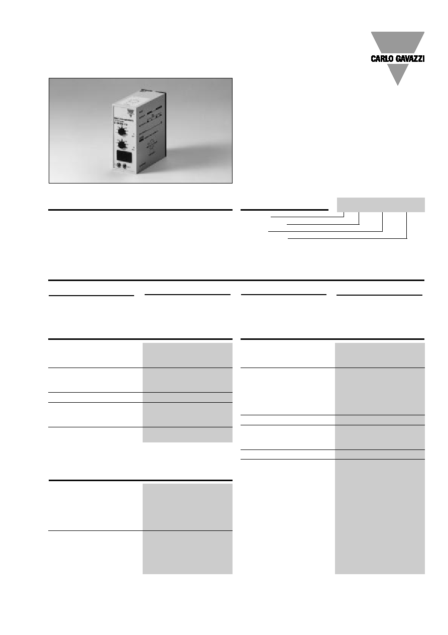
Start attempt/alarm, plug-in
time relay with 2 separate out-
put relays. Used when start-
ing combustion engines con-
nected to generators. May
operate with 1-6 selectable
start attempts. Adjustable
duration of start attempts and
pulse between start attempts.
Failure to start causes an out-
put signal.
∑ Automatic start
∑ No. of start attempts: 1-6
∑ Duration of attempts: 1.5-30 s
∑ Pause between attempts: 3-60 s
∑ Repeatability deviation:
1%
∑ Separate relay contact for activation of start relay
∑ Separate relay for alarm if selected no. of start
attempts fails
∑ Output: 2 x 10A SPDT relay
∑ Plug-in type module
∑ S -housing
∑ LED-indication for both relays on
∑ DC power supply
Start Attempt/Alarm
Type S 109
Product Description
Ordering Key
Type Selection
Time Specifications
Output Specifications
Supply Specifications
S 109 256 712

2
Specifications are subject to change without notice (25.10.99)
S 109
Start function
The power supply is applied.
Relay A operates immediately.
After expiration of the set time
period (T1), relay A releases
for the set time period (T2).
The cycle with active periods
and pause periods continues
from 1 to 6 times as set on the
DIP-switch or until power sup-
ply is interrupted by generator
start.
Alarm function
Relay B changes to operating
position after conclusion of
the last failed start attempt
(e.g. 2 set start attempts) and
remains in this position until
power supply is interrupted.
Power ON delay
200 ms
Power OFF delay
100 ms
Indication for
Output 1 ON
LED, red
Output 2 ON
LED, red
Environment
Degree of protection
IP 20 B
Pollution degree
2 (IEC 60664)
Operating temperature
-20∞ to +50∞C (-4∞ to +122∞F)
Storage temperature
-50∞ to +85∞C (-58∞ to +185∞F)
Weight
125 g
Approvals
UL, CSA
Power supply
Alarm
B
Start
A
Time setting
Upper knob on housing:
Duration of start attempts
(T1): 1.5 to 30 s.
Lower knob on housing:
Duration of pause between
start attempts (T2): 3 to 60 s.
Number of start attempts
1 to 6 attempts, set on DIP-
switches.
DIP-switch 1 ON: 1 attempt.
DIP-switch 2 ON: 2 attempts.
Etc.
Sockets
S 411
Hold down spring
HF
Mounting rack
SM 13
Socket covers
BB 4
Potentiometer lock
PL 2
Front mounting bezel
FRS 2
For further information refer to "Accessories".
Power supply
Relay A ON, pins 1 & 3
Relay B ON, pins 9 & 11
If more than one DIP-switch
is ON, the lowest is given pri-
ority.
DIP-switches for selecting
function are placed behind a
small removable front plate
on the time relay.
1 2 3 4 5 6
ON
OFF
General Specifications
Mode of Operation
Time Setting
Wiring Diagram
Accessories
Operation Diagram
Generator Start