Specifications are subject to change without notice (22.12.99)
1
Timers
Product Description
Housing
Type/Function
Output
Power supply
Time ranges
0.15 -
3 s
Selectable by DIP-switch
0.6 -
12 s
5
- 100 s
40
- 800 s
Time range accuracy
0 to +10% max.
min. actual time
min.
set time
Repeatibility deviation
1%
Time variation
Within rated power supply
0.05%/V
and ambient temperature
0.2%/�C
Reset
Power supply interruption min.
Time and/or relay
200 ms
Plug
Output
Time range
Supply: 24 VAC
Supply: 115 VAC
Supply: 230 VAC
Supply: 24 VDC
Circular
2 x SPDT 0.15 s - 800 s
S 1151 256 024
S 1151 256 115
S 1151 256 230
S 1151 256 724
Output
2 x SPDT relay
Basic electrical insulation
250 VAC (rms) (contact/
elec., contact/contact)
Contact ratings (Ag-CdO)
� (micro gap)
Resistive load
AC 1
10 A/250 VAC (2500 VA)
DC 1
1 A/250 VDC (250 W)
or
10 A/25 VDC (250 W)
Small inductive loads AC 15
2.5 A/230 VAC
DC 13
5 A/24 VDC
Mechanical life
2.5 x 10
5
operations
Electrical life
2.5 x 10
5
operations
Operating frequency
7200 operations/h
Insulation voltages
Rated insulation voltage
2.0 kVAC (rms) (cont./elec.)
Rated transient protection volt. 4 kV (1.2/50 �s) (cont./elec.)
(IEC 60664)
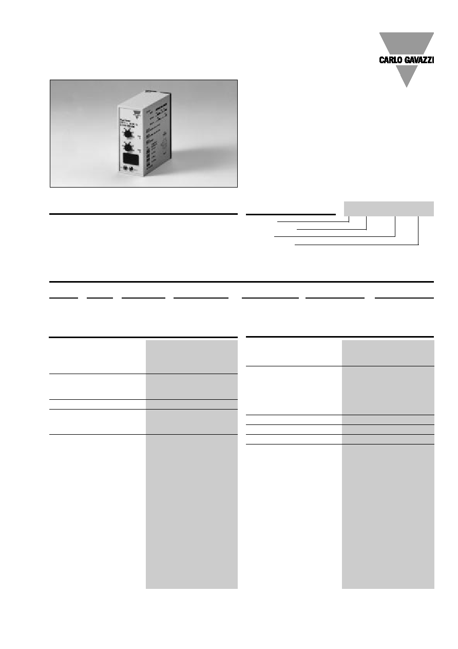
Two-state delay on operate,
plug-in time relays. Often
used in applications with
pumps where a delay is nec-
essary at start and restart,
and if the capacity of the first
pump is insufficient no. 2
starts after a given delay. This
may be done automatically
by means of the SG 125.
� 4 selectable time ranges: 0.15 s to 800 s
� Automatic start
� Separate time-setting for the two delay on operate
time periods
� Repeatibility deviation:
1%
� Selection of order of relays
� Output: 2 x 10 A SPDT relay
� Plug-in type module
� S-housing
� LED-indication for relay 1 and relay 2 on
� AC or DC power supply
Two-state Delay on Operate
Type S 1151
Ordering Key
Type Selection
Time Specifications
Output Specifications
S 1151 256 024
2
Specifications are subject to change without notice (22.12.99)
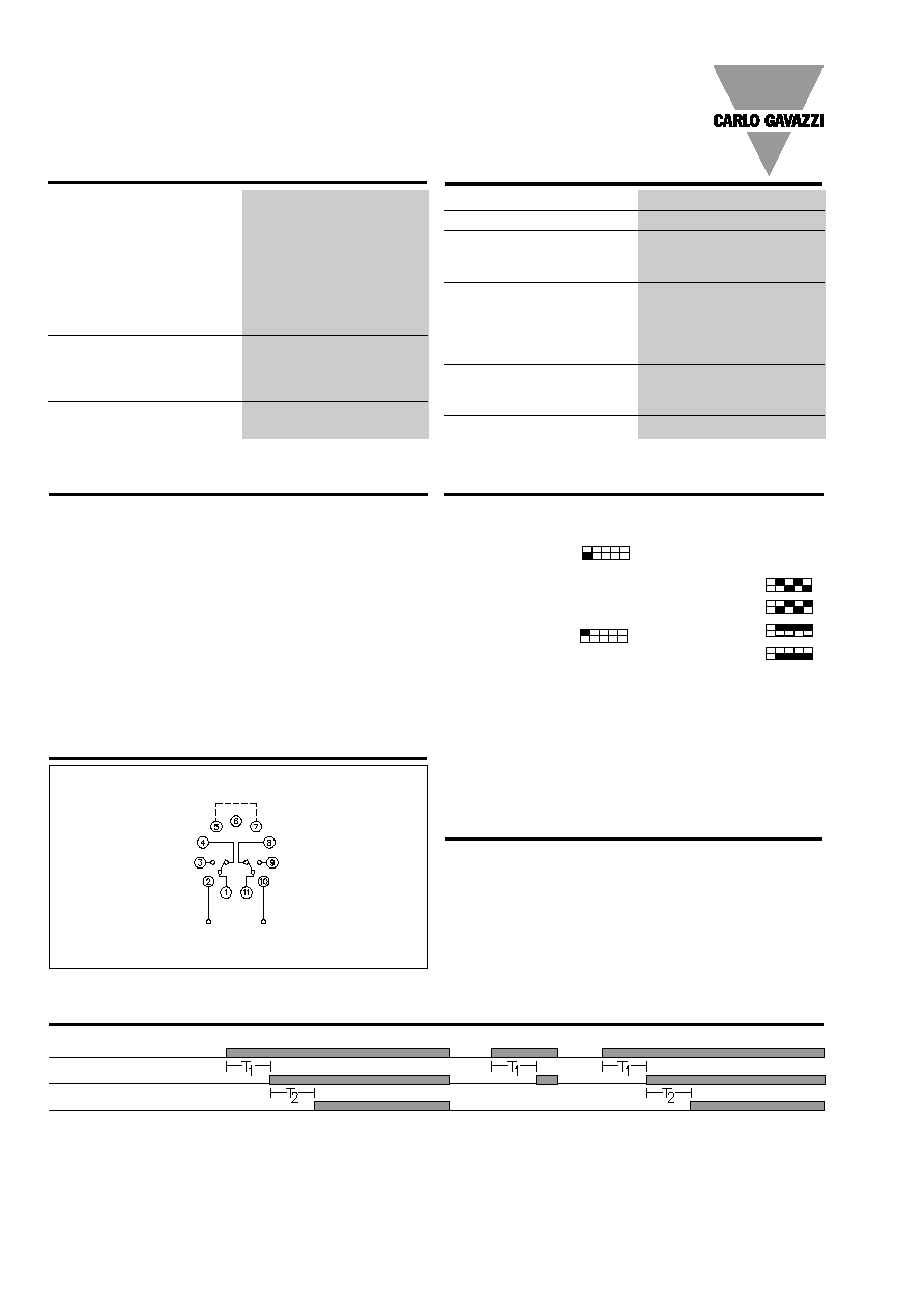
Mode of Operation
The time period for relay 1
starts when power supply is
applied.
At the end of the set time pe-
riod, relay 1 operates and the
time period for relay 2 starts.
At the end of the second set
time period, relay 2 operates
and both relays will not re-
lease until power supply is
interrupted.
S 1151
Wiring Diagram
Power supply
Ext. reversion
Power supply
Relay 1 ON
Relay 2 ON
Power supply AC types
Installation cat. III (IEC 60664)
rated operational voltage
through pins 2 & 10
230
230 VAC � 15%, 45 to 65 Hz
115
115 VAC � 15%, 45 to 65 Hz
024
24 VAC � 15%, 45 to 65 Hz
Drop-out tolerance
40 ms
Rated insulation voltage
2.0 kVAC (rms)
Rated transient protection volt. 4 kV (1.2/50 �s)
(line/neutral)
Power supply DC types
Installation cat. III (IEC 60664)
Rated operational volt.
724
24 VDC � 15% (pin 2 pos.)
Rated insulation voltage
None
Rated transient protection volt. 800 V (1.2/50 �s)
Consumption
AC supply
2.5 VA
DC supply
1.5 W
Power ON delay
200 ms
Power OFF delay
200 ms
Indication for
Output 1 ON
LED, red
Output 2 ON
LED, red
Environnment
Degree of protection
IP 20 B
Pollution degree
2 (IEC 60664)
Operating temperature
-20� to +50�C (-4� to +122�F)
Lagertemperatur
-50� to +85�C (-58� to +185�F)
Weight
AC supply
200 g
DC supply
125 g
Approvals
UL, CSA
Selection of function
DIP-switch selector 1
Relay 1 operates
first (pins 1,3 and 4), when the
DIP-switch at the front of the
housing is in OFF-position
Relay 2 operates
first (pins 8,9 and 10) when the
DIP-switch at the front of the
housing is in ON-position
Reverse function (pins 5 and 7)
Selection of time-range
T1: DIP-switch selector (2&3)
T2: DIP-switch selector (4&5)
0.15 - 3 s
0.6 - 12 s
5
- 100 s
40
- 800 s
Time setting
Knob-adjustable on scale in
per cent of max. time. DIP-
switch for selecting function
and time are placed behind a
small removable front on the
front of the time relay.
1 2 3 4 5
1 2 3 4 5
The order of the relays can be
inverted by means of a DIP-
switch at the front of the hous-
ing or by interconnecting pins
5 and 7 on the socket.
If power supply is interrupted
for at least 200 ms, the time
relay and time circuit are re-
set and the relay is ready for a
new time period.
Sockets
S 411, D 411 B
Hold down spring
HF
Mounting rack
SM 13
Socket covers
BB 4, BB 5B
Potentiometer lock
PL 2
Front mounting bezel
FRS 2
For further information refer to "Accessories".
1 2 3 4 5
Supply Specifications
General Specifications
Function/Time Setting
Accessories
Operation Diagram