Specifications are subject to change without notice (25.10.99)
1
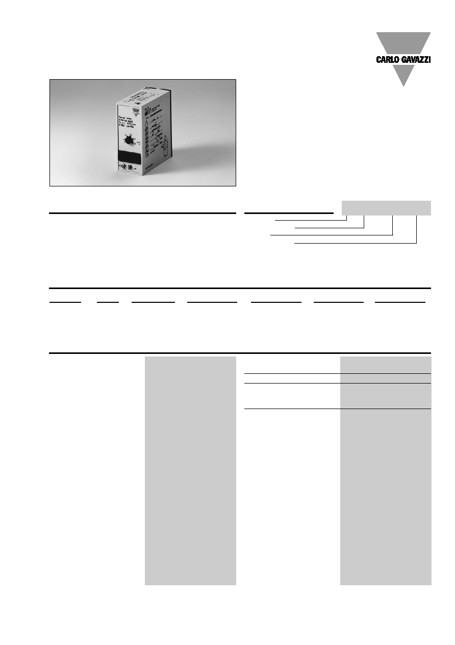
Timers
Multi delay on operate and
multi interval, plug-in time
relay with 20 selectable time
ranges up to 220 h and 12
selectable modes of opera-
tion. Extensively applicable
Housing
Type/function
Output
Power supply
due to the combination and
variety of voltages, functions
and time ranges.
Accuracy
0 to +10% on max.
min. actual time
set time
Repeatability deviation
1%
Time variation
Within rated power supply
0.05%/V
and ambient temperature
0.2%/∞C
Reset
Time and relay
Intercon. pins 5 & 7
pin 5 pos., 24 VDC, 6 mA
Pulse duration
10 ms
Power supply interruption
Min. 200 ms
Sensor supply output
24 VDC, 15 mA
pin 6 & 7
pin 6 pos.
Time ranges
0.15 s -
1.5 s
Selectable by DIP-switch
0.3 s -
3 s
0.6 s -
6 s
1.2 s - 12 s
2.5 s - 25 s
5 s
- 50 s
10 s
- 100 s
20 s
- 200 s
40 s
- 400 s
1.3 m - 13 m
2.6 m - 26 m
5 m
- 50 m
10 m
- 100 m
20 m
- 200 m
40 m
- 400 m
1.4 h - 14 h
2.8 h - 28 h
5.5 h - 55 h
11 h
- 110 h
22 h
- 220 h
Plug
Output
Time range
Supply: 24 VAC
Supply: 115 VAC
Supply: 230 VAC
Supply: 24 VDC
Circular
SPDT
0.15 s-220 h
S 1221 156 024
S 1221 156 115
S 1221 156 230
S 1221 156 724
DPDT
0.15 s-220 h
S 1221 166 024
S 1221 166 115
S 1221 166 230
S 1221 166 724
∑ 6 selectable delay on operate functions
∑ 6 selectable interval timer functions
∑ 20 selectable time ranges: 0.15 s to 220 hrs
∑ Knob-adjustable time within range
∑ Oscillator-controlled time circuit
∑ Repeatability deviation:
1%
∑ Direct connection for NPN sensor
∑ Output: 10 A SPDT relay or 8 A DPDT relay
∑ Plug-in type module
∑ S-housing
∑ LED-indication for relay and power supply on
∑ AC or DC power supply
Multi-function
Type S 1221
Product Description
Ordering Key
Type Selection
Time Specifications
S 1221 156 024
2
Specifications are subject to change without notice (25.10.99)
S 1221
Power supply AC types
Installation cat. III (IEC 60664)
Rated operational voltage
through pins 2 & 10
230
230 VAC ± 15%, 45 to 65 Hz
115
115 VAC ± 15%, 45 to 65 Hz
024
24 VAC ± 15%, 45 to 65 Hz
Drop-out tolerance
40 ms
Rated insulation voltage
2.0 kVAC (rms)
(supply/elec.)
Rated transient protection volt. 4 kV (1.2/50 µs)
(line/neutral)
Power supply DC type
Installation cat. III (IEC 60664)
Rated operational voltage 724
24 VDC ± 15% (pin 2 pos.)
Rated insulation voltage
None
Rated transient protection volt. 4 kV (1.2/50 µs)
Consumption
AC supply
2.5 VA
DC supply
1.5 W
S 1221 156
S 1221 166
Output
SPDT relay
DPDT relay
Basic electrical insulation
250 VAC (rms) (contact/electronics)
250 VAC (rms) (contacts/elec., contact/contact)
Contact ratings (AgCdO)
µ (micro gap)
µ (micro gap)
Resistive loads
AC 1
10 A/250 VAC (2500 VA)
8 A/250 VAC (2000 VA)
DC 1
1 A/250 VDC (250 W)
0.4 A/250 VDC (100 W)
or
10 A/25 VDC (250 W)
4 A/25 VDC (100 W)
Small inductive loads
AC 15 2.5 A/230 VAC
2.5 A/230 VAC
DC 13 5 A/24 VDC
5 A/24 VDC
Mechanical life
30 x 10
6
operations
30 x 10
6
operations
Electrical life
AC 1
2.5 x 10
5
operations (at max. load)
2.5 x 10
5
operations (at max. load)
Operating frequency
7200 operations/h
7200 operations/h
Insulation voltages
Rated insulation voltage
2.0 kVAC (rms) (contact/electronics)
2.0 kVAC (rms) (contact/electronics)
Rated transient protection volt.
4 kV (1.2/50 µs) (contact/electronics) (IEC 60664)
4 kV (1.2/50 µs) (contact/electronics) (IEC 60664)
Function 1
Interval timer - man. start -
no restart - man. time reset
The relay operates when in-
terconnecting pins 5 and 7.
When disconnecting pins 5
and 7, the time period starts.
At the end of set time period,
the relay releases. Intercon-
nection of pins 5 and 7 for at
least 10 ms during the time
period, causes the time to
reset. No restart when time
period has expired.
Function 2
Like function 1, but with man-
ual start.
Function 3
Interval timer - man. start -
man. restart - no time reset
The relay operates and the
time period starts when inter-
connecting pins 5 and 7 for at
least 10 ms. At the end of set
time period, the relay releases
regardless of the connection
between pins 5 and 7. Re-
newed connection between
pins 5 and 7 causes the relay
to operate and a new time pe-
riod starts.
Function 4
Delay on operate - man.
start - no restart -
man. time reset
The time period starts when
disconnecting pins 5 and 7.
At the end of the set time
period, the relay operates.
When interconnecting pins 5
and 7 for at least 10 ms du-
ring the time period, the time
is reset and a new time period
starts when pins 5 and 7 are
disconnected. No restart
when the time period has ex-
pired.
Function 5
Delay on operate - man.
start - man. restart - time
reset
Otherwise like function 4.
Function 6
Delay on operate - man.
start - man. restart - no time
reset
The time period starts when
connecting pins 5 and 7. At
the end of the set time period,
the relay operates. When con-
necting pins 5 and 7 after the
time period, the relay releases
and a new time period starts.
Power ON delay
200 ms
Power OFF delay
200 ms
Indication for
Power supply ON
LED, green
Output ON
LED, red
Environment
Degree of protection
IP 20 B
Pollution degree
2 (IEC 60664)
Operating temperature
-20∞ to +50∞C (-4∞ to +122∞F)
Storage temperature
-50∞ to +85∞C (-58∞ to +185∞F)
Weight
AC types
200 g
DC types
125 g
Approvals
CSA
Output Specifications
Supply Specifications
General Specifications
Mode of Operation
Specifications are subject to change without notice (25.10.99)
3
Mode of Operation (cont.)
Function 7
Interval timer - aut. start -
no restart - man. time reset
The relay operates and the
time period starts when pow-
er supply is applied. At the
end of the set time period, the
relay releases. When intercon-
necting pins 5 and 7 for at
least 10 ms during the time
period, the time is reset and a
new time period starts when
pins 5 and 7 are disconnect-
ed.
No restart when the time peri-
od has expired.
Function 8
Like function 2, but with auto-
matic start after applying
power supply.
Function 9
Like function 3, but with auto-
matic start after applying
power supply.
Function 10
Delay on operate - aut. start
- no restart - man. time
reset
The time period starts when
power supply is applied. At
the end of the set time period,
the relay operates. When in-
terconnecting pins 5 and 7 for
at least 10 ms during the time
period, the time is reset and a
new time period starts when
pins 5 and 7 are dis-
connected.
No restart when the time peri-
od has expired.
Function 11
Like function 5, but with auto-
matic start after applying
power supply.
Function 12
Like function 6, but with auto-
matic start after applying
power supply.
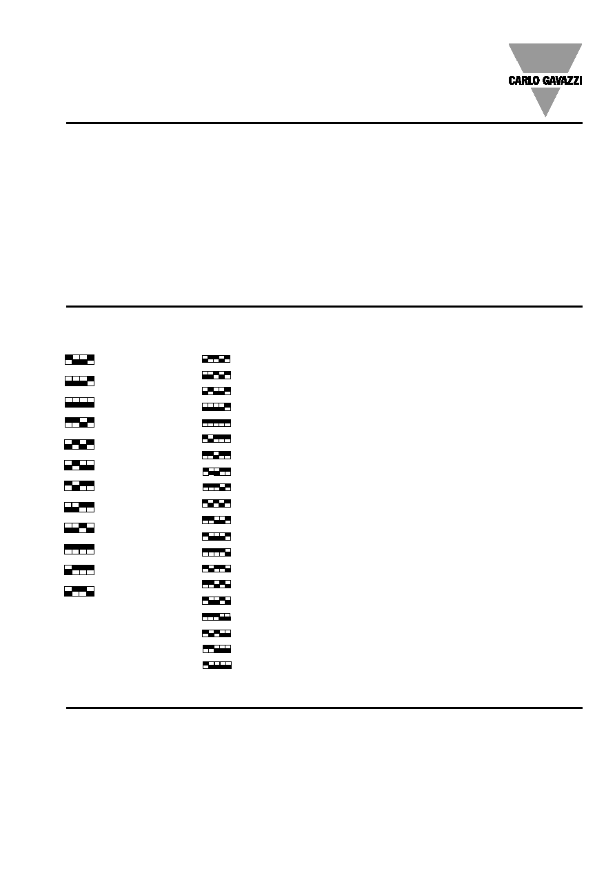
Selection of function
DIP-switch selector (1 - 4).
1 2 3 4
1. Interval timer - man. start -
man. time reset - no restart
2. Interval - man. start -
man. restart and time reset
3. Interval timer - man. start -
man. restart - no. time reset
4. Delay on operate - man. start -
man. time reset - no restart
5. Delay on operate - man. start -
man. restart and time reset
6. Delay on operate - man. start -
man. restart - no time reset
7. Interval timer - aut. start -
man. time reset - no restart
8. Interval timer - aut. start -
man. restart and time reset
9. Interval timer - aut. start -
man. restart - no time reset
10. Delay on operate - aut. start -
man. time reset - no restart
11. Delay on operate - aut. start -
man. restart and time reset
12. Delay on operate - aut. start -
man. restart - no time reset
S 1221
5 6 7 8 9
0.15 s - 1.5 s
0.3 s
- 3 s
0.6 s
- 6 s
1.2 s
- 12 s
2.5 s
- 25 s
5 s
- 50 s
10 s
- 100 s
20 s
- 200 s
40 s
- 400 s
1.3 m - 13 m
2.6 m - 26 m
5 m
- 50 m
10 m
- 100 m
20 m
- 200 m
40 m
- 400 m
1.4 h
- 14 h
2.8 h
- 28 h
5.5 h
- 55 h
11 h
- 110 h
22 h
- 220 h
Selection of time range
DIP-switch selector (5 - 9).
Time setting
Knob-adjustable on scale in
per cent of max. time.
DIP-switches for selecting
function and time are placed
behind a small removable
front plate on the time relay.
Sockets
S 411
Hold down spring
HF
Mounting rack
SM 13
Socket covers
BB 4
Front mounting bezel
FRS 2
Potentiometer lock
PL 3
All 3-wire sensor types with
NPN open collector output.
For further information refer to
"Accessories". For other
AC/DC voltages refer to
"General Information".
Function/Time Setting
Accessories
4
Specifications are subject to change without notice (25.10.99)
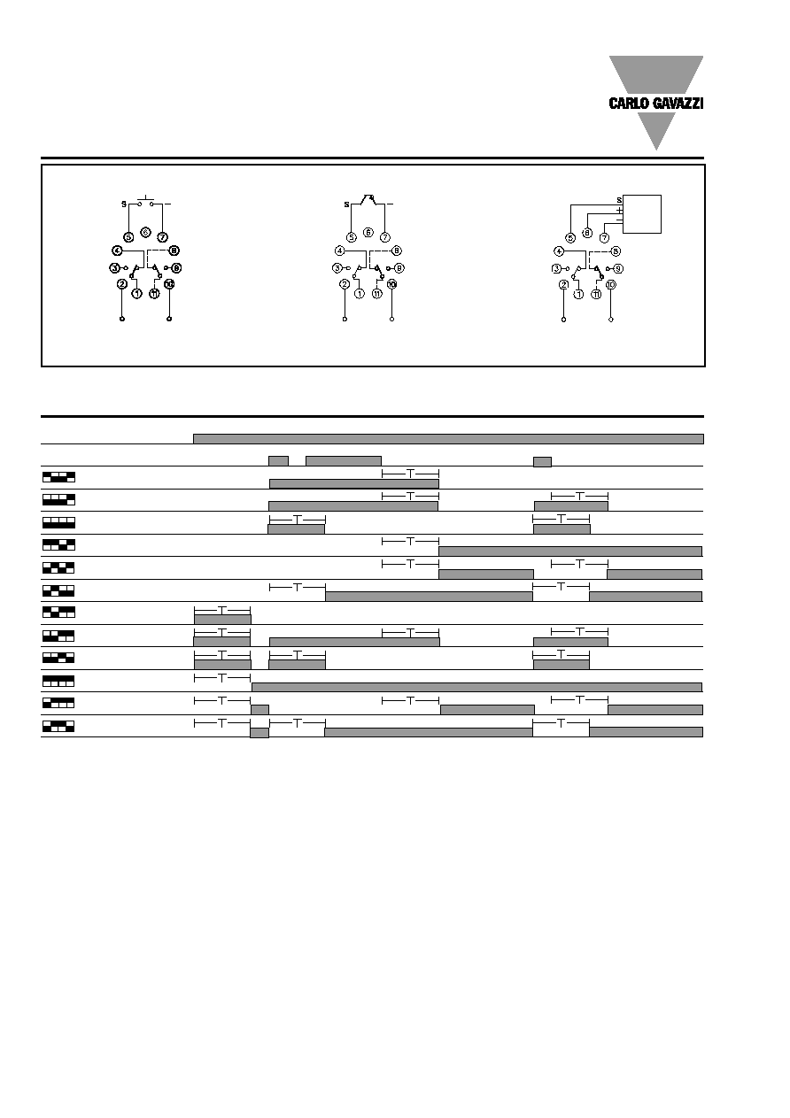
Power supply
S 1221 156, S 1221 166
3-wire
NPN
sensor
S 1221
Open collector
Contact
Sensor
Diagram Operation
Power supply
1 2 3 4
Pulse (pins 5 & 7)
1. Relay on
2. Relay on
3. Relay on
4. Relay on
5. Relay on
6. Relay on
7. Relay on
8. Relay on
9. Relay on
10. Relay on
11. Relay on
12. Relay on
Wiring Diagrams
Power supply
S 1221 156, S 1221 166
Power supply
S 1221 156, S 1221 166