Specifications are subject to change without notice (25.10.99)
1
Timers
∑ µP-based digital multi-function timer
∑ 10 functions within delay on operate, interval timer,
symmetrical recycler, recycler with fixed ON time,
time period multiplier
∑ Time ranges: 0.01 s to 99 h
∑ Digital trigger input for time start and reset
∑ Time stop input
∑ Four yellow LEDs each indicating 25% of remaining
time
∑ Connection for NPN sensor
∑ Plug-in module, S-housing
∑ Output: 5 A SPDT relay
∑ LED-indication for relay and power supply ON
∑ AC or DC power supply
Product Description
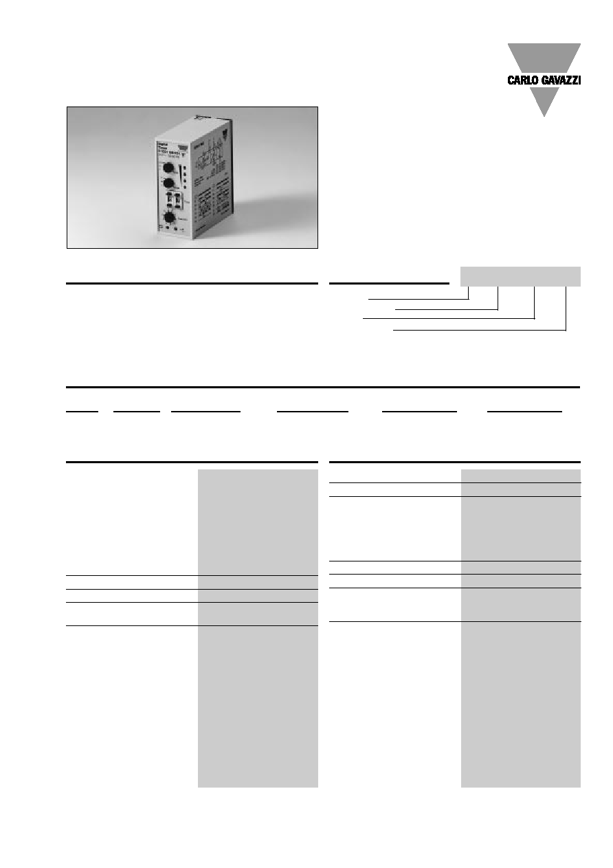
Plug-in, µP-based, multifunc-
tion time relay with 10 select-
able modes of operation and
time ranges from 10 ms to 99
h. Function and time range
setting by 3 rotary switches in
Ordering Key
Housing
Type/function
Output
Power supply
the front. Time setting by two
digital thumb-wheel switches
in the front. Time controlled
by contact, open collector
output (NPN) or power supply.
Type Selection
Plug
Output
Supply: 24 VAC
Supply: 115 VAC
Supply: 230 VAC
Supply: 24 VDC
Circular
SPDT
S 1331 156 024
S 1331 156 115
S 1331 156 230
S 1331 156 724
Output Specifications
Output
SPDT
Rated insulation voltage
250 VAC (rms) (cont./elect.)
Contact ratings (AgCdO)
µ (micro gap)
(IEC 60947-5-1/IEC 60337)
Resistive loads
AC 1
5 A, 250 VAC
DC 1
5 A, 24 VDC
Small inductive loads AC 15
2 A, 250 VAC
DC 13
3 A, 24 VDC
Mechanical life
40 x 10
6
operations
Electrical life
10
5
operations (at max. load)
Operating frequency
typ. 50 Hz
Operating time
< 10 ms
Release time (at nom. supply) < 6 ms
Dielectric strength
Dielectric (AC rms)
test voltage
2.0 kVAC (rms) (cont./elect.)
Rated impulse withstand
voltage
4 kV (1.2/50 µs) (cont./elect.)
(IEC 60664)
Time Specifications
Time ranges
Selectable by rotary switches 0.01 - 0.99 s
0.1 - 9.9 s
1 - 99
s
0.01 - 0.99 m
0.1 - 9.9 m
1 - 99
m
0.01 - 0.99 h
0.1 - 9.9
h
1 - 99
h
Accuracy
0.5%, ±20 ms
Repeatability deviation
0.01%
Time variation
within rated ambient temp.
0.008%/∞C
Reset
Time and/or relay
Interconnect pins 5 & 7
24 VDC, 5 mA
Time stop
Interconnect pins 7 & 8
24 VDC, 5 mA
Input interruption
10 ms
Sensor supply output
Pins 6 & 7, pin 6 positive
24 VDC, 10 mA
Digital Multi-function
Type S 1331
S 1331 156 230

2
Specifications are subject to change without notice (25.10.99)
Supply Specifications
Power supply AC types
Overvoltage cat. III (IEC 60664)
Rated operational voltage
through pins 2 & 10
230
230 VAC ±15%, 45 to 65 Hz
115
115 VAC ±15%, 45 to 65 Hz
024
24 VAC ±15%, 45 to 65 Hz
Voltage interruption
40 ms
Rated insulation voltage
250 VAC (rms)
Rated operational power
3.0 VA
Rated impulse withstand voltage 4 kV (1.2/50 µs) (line/neutral)
Power supply DC type
Overvoltage cat. III (IEC 60664)
Rated operational volt. 724
24 VDC ±15% (pin 2 pos.)
Rated insulation voltage
None
Rated operational power
1.5 W
Rated impulse withstand voltage 800 V (1.2/50 µs)
General Specifications
Power ON delay
150 ms
Power OFF delay
200 ms
Indication for
Power supply ON
LED, green
Output ON
LED, yellow
Remaining time to elapse
4 LEDs, yellow, 25% each
Environment
Degree of protection
IP 20 B
Pollution degree
2 (IEC 60664)
Operating temperature
0∞ to +50∞C (+34∞ to +122∞F)
Storage temperature
-50∞ to +85∞C (-58∞ to +185∞F)
Weight
AC supply
200 g
DC supply
125 g
Approvals
UL, CSA
S 1331
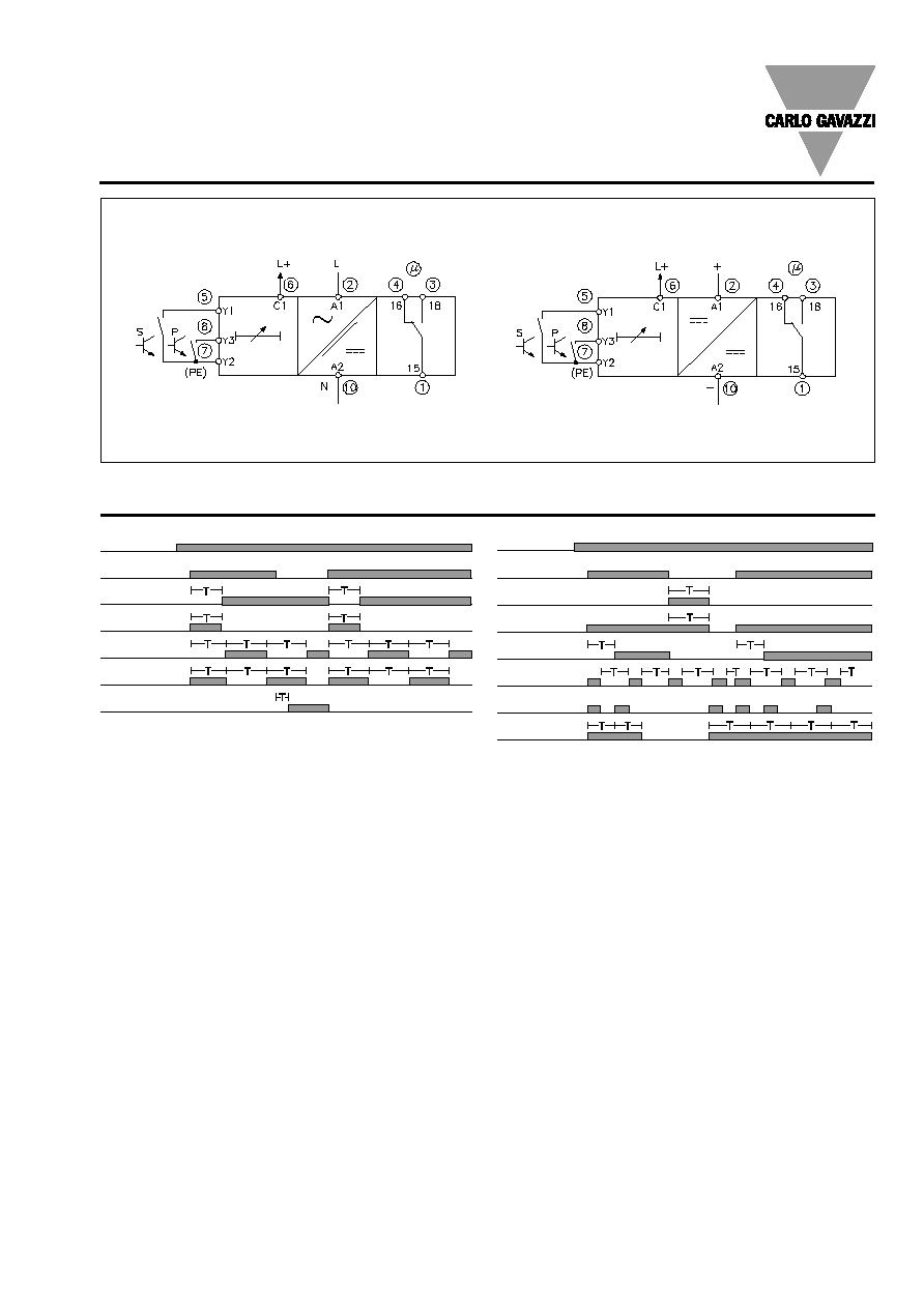
Mode of Operation
In connection with all func-
tions automatic start is pos-
sible by permanent intercon-
nection of pins 5 & 7.
Function 0: Delay on operate,
leading edge, man. start,
man. restart, man. time reset.
Function 1: Interval timer,
leading edge, man. start,
man. restart, man. time reset.
Function 2:
Symmetrical
recycler, OFF-time first, lea-
ding edge, man. start, man.
restart, no time reset.
Function 3:
Symmetrical
recycler, ON-time first, lea-
ding edge, man. start, man.
restart, no time reset.
Function 4: Delay on operate,
trailing edge, man. start, man.
restart, man. time reset.
Function 5: Interval timer,
trailing edge, man. start, man.
restart, man. time reset.
Note: The output relay only
operates when the time peri-
od is running.
Function 6: Interval timer,
trailing edge, man. start, man.
restart, man. time reset.
Function 7: Delay on operate,
leading edge, man. start,
man. restart, man. time reset.
Note: The relay releases on
trailing edge, which means
the trigger pulse must be of
longer duration than the time
period.
Function 8: Recycler with fix-
ed ON-time, leading edge,
man. start, man. restart, no
time reset. Fixed ON-time:
approx. 0.5 sec.
Function 9: Time period mul-
tiplier, leading edge, man.
start, man. restart, man. time
reset.
Note: Each pulse input adds
the set time the total timing
period. Max. time period
memory is 256 pulses.
Time stop function: By inter-
connection of pins 7 & 8 the
time function stops, and the
output relay remains either
released or operated. By dis-
connection of pins 7 & 8 the
remaining time continues to
elapse.
Accessories
Function and Time Setting
Adjustable time setting by two
digital thumb-wheel switches
(1-99)
Upper knob:
Time period multiplier x 0.01,
x 0.1 and x 1.0.
Socket
S 411
Hold down spring
HF
Mounting rack
SM 13
Socket cover
BB 4
Front mounting bezel
FRS 2
All 3/4-wire sensor types with NPN open collector output.
For further information refer to "Accessories".
For other AC/DC voltages refer to "General Information".
Centre knob:
Selection of time range
(seconds, minutes and hours).
Lower knob:
Selection of function.