Specifications are subject to change without notice (25.06.99)
1
Supply to photoelectric switch
Emitter (cont.)
Supply voltage (open loop)
7 V square wave
Current
300 mA short-circuit
protected
Output resistance
10
Receiver
Rx1: Pin 4
Rx2: Pin 7
Rx3: Pin 8
Shield: Pin 5 (common)
Supply voltage (open loop)
5 VDC
Short-circuit current
10 mA
Input resistance
470
Sensitivity
∑
2 ranges,
(% of S
n
)
DIP-switch selectable
- low sensitivity (25%)
- high sensitivity (100%)
∑
Sensitivity adjustment
with 270∞:
Turn knob on CH 1, 2, 3
Note:
∑
Maximum range indicated
on photoelectric switch
data sheet in high sensi-
tivity range only
∑
Operation within low sen-
sitivity range, increases
ambient light and cross-
talk immunity
Rated operational voltage (U
B
)
pins 2 & 10
DC
13.5 to 33 VDC
AC
13.5 to 33 VAC, 45 to 65 Hz
Rated operational power
AC supply
5 VA
DC supply
5 W
Power ON delay (t
v
)
< 300 ms
Output
Contact Rating (AgCdO)
Resistive loads
AC 1
1.5 A/100 VAC
DC 1
1.5 A/30 VDC
Small induc. loads
AC 15 1.5 A/100 VAC
DC 13 1.5 A/30 VDC
Mechanical life (typical)
20 x10
6
operations at
18000 imp/H
Electrical life (typical)
300000 operating at
220 VAC - 2A resistive load
Output function
Relay Make function
Protection, outputs
Reverse polarity, short-circuit,
transients
Supply to photoelectric switch
Emitter
Tx1: Pin 1
Tx2: Pin 9
Tx3: Pin 6
Shield: Pin 11 (common)
Photoelectrics
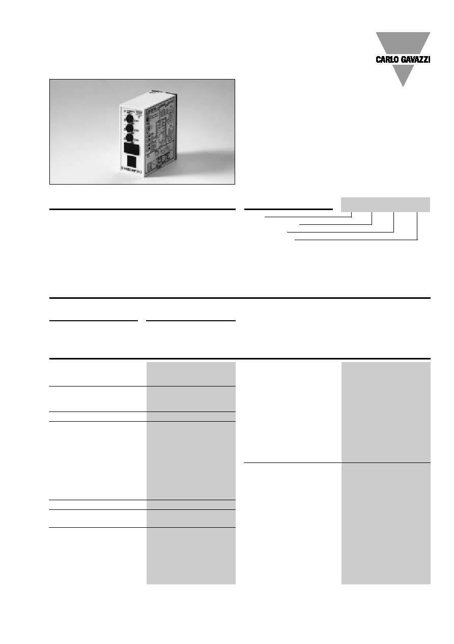
Amplifier, µ-Processor Controlled
Type S1430 RAL, 3 Inputs/3 Relay Outputs
Product Description
Ordering Key
Type
Special function
Output type
Power supply
µ-Processor controlled ampli-
fier for 3 sets of photoelec-
tric sensors, type MOFTR,
MKFTR, MIFTR or MHFTR.
Utilising an 11-pin circular
plug for easy connection.
Relay outputs (NO). Self-
diagnostics for system test.
Protected against reverse
wiring or cross talk from
adjecent photoelectrics. Mul-
ti-voltage power supply.
Sensitivity is individually
adjustable for each set of
photoelectrics.
∑ µ-Processor controlled
∑ Amplifier unit for 3 sets of photoelectrics
∑ 3 independent outputs with 1 x Relay SPDT, make
switching funktion
∑ Self-diagnostic functions
∑ Alignment failure indication
∑ Multivoltage 15 to 30 VAC/DC
∑ Modulated and synchronized light
∑ Adjustable sensitivity for each channel
∑ LED indications: supply, outputs, signal quality
∑ 11-pin plug-in housing
∑ For 115 or 230 VAC use power supplys from SS120 series
Type Selection
Plug type
Ordering no.
Supply: 15 - 30 VAC/DC
Circular, 11 pins
S 1430 RAL 915
Specifications
S14 30 RAL 915

2
Specifications are subject to change without notice (25.06.99)
Object present
Yes
No
No
Dirt on lenses,
misaligned or
--
No
Yes
1)
sensitivity too low
Output LED yellow
OFF
ON
ON
Level LED red
OFF
OFF
Output OFF
ON
ON
Operating frequency (f)
Light/dark ratio 1:1
12.5 Hz
Response time
OFF-ON (t
ON
)
30 ms
ON-OFF (t
OFF
)
30 ms
Multiplex cycle time
20 ms
Indication
Supply ON
LED, green
Output ON
LED, yellow
Signal quality
LED, red
Multiplex activated
LED, yellow
Environment
Overvoltage category
III (IEC 60664)
Degree of protection
IP 20 (IEC 60529, 60947-1)
Pollution degree
3 (IEC 60664/60664A, 60947-1)
Temperature
Operating
-20∞ to +50∞C (-4∞ to +122∞F)
Storage
-50∞ to +85∞C (-58∞ to 185∞F)
Weight
150 g
CE-marking
Yes
S 1430 RAL
Specifications (cont.)
Truth Table
Make switching
ON
or
flashing
1)
Under normal operating conditions, the red level indication
LED has to be OFF. The level indication LED will turn on
shortly each time an object enters or exits the sensing
zone, even if the photoelectric switch is correctly installed
and adjusted.
Procedure for Test Functions (Dip-switch Selection)
Transmitter test
(switch 1 in the up position)
When switch 1 is placed in
the up position all yellow and
red LED's on the front of the
unit will flash simultaneously.
Once the test is completed
(approx. 3 scans) and a
wiring fault is detected, such
as reverse polarity or short-
circuit, the transmitter that
has the fault condition will
be indicated by the red LED
being continuously ON. If a
fault condition is not existing
then only the yellow LED will
be ON. If a fault exists, cor-
rect the fault condition and
then repeat the test, this will
ensure proper wiring has
been done. Always
reset
switch 1 for normal opera-
tion of system when testing
completed.
Receiver test
(switch 2 in the up position)
When switch 2 is placed in
the up position all yellow and
red LED's on the front of the
unit will flash simultaneously.
Once the test is completed
(approx.
3 scans) and a
wiring fault is detected, such
as reverse polarity or short-
circuit, the receiver that has
the fault condition will be
indicated by the red LED
being continuously ON. If a
fault condition is not existing
then only the yellow LED will
be ON. If a fault exists, cor-
rect the fault condition and
then repeat the test, this will
ensure proper wiring has
been done. Always
reset
switch 2 for normal opera-
tion of system when testing
completed.
Function test
(switch 1 and 2 in the up position)
When switch 1 and 2 are
both placed in the up posi-
tion (simultaneously) the yel-
low and red LED's on the
front of the housing will
begin to flash simultane-
ously and then the LED's
LED Indication
Yellow LED ON
Red LED OFF
Yellow LED ON
Red LED ON
Yellow LED OFF
Red LED ON
Yellow LED
System Test OK
}
Tx's and Rx's mismatched,
e.g. Rx3 seeing Tx1
}
}
Alignment error or beam
obstructed by object
!
!
!
will cycle from channel 1 to
channel 2 and then to chan-
nel 3. Once the complete
system scan is done the
indication of the system
condition will be displayed
(see below). System test will
continue until switches 1
and 2 are reset.
}
When max. 3 amplifiers are
linked the LED flashes
Multiplex mode is when
having up to 3 amplifiers
linked together via connecti-
on no. 3 in the 11-pole
socket. The system acti-
vates amplifier no. 1 channel
1, 2 and 3. Then amplifier
no. 2 channel 1, 2 and 3 and
finally amplifier no. 3 chan-
nel 1, 2 and 3. Then back to
amplifier no. 1 etc. Operat-
ing frequency in a multiplex
system is divided with the
number of amplifiers used.
Response time in a multi-
plex system is multiplied
with the number of amplifi-
ers used. When working in a
multiplex system the yellow
LED flashes.
Multiplex Mode
( )

Specifications are subject to change without notice (25.06.99)
3
S 1430 RAL
Operation Diagram
Power supply
Object present
Signal quality
!
Wiring Diagrams
A B C D E F
Output
Wire colour
coding
A: white
B:
Output 1 (max. 30 VDC, 100 VAC, 1.5A)
black
C: red
D:
Output 2 (max. 30 VDC, 100 VAC, 1.5A)
green
E: yellow
F:
Output 3 (max. 30 VDC, 100 VAC, 1.5A)
blue
ON sockets
1: Transmitter 1
2: Supply (+ VDC)
3: Multiplex
4: Receiver 1
5: GND (Receivers)
6: Transmitter 3
7: Receiver 2
8: Receiver 3
9: Transmitter 2
10: Supply (- VDC)
11: GND (Transmitters)
Power Supply
8
9
10
11
7
6
5
4
3
1
2
Rx 1
Rx 2
Rx 1
Rx 3
Tx 1
Tx 2
Rx 1
Tx 3
( )
Multiplex
Make switching
Signal strength
Time
}
}
}
Dimensions
( )
35
80
84
75
4
5
DIP-Switch (located behind cover):
1: Make/break CH 1 output
2: Make/break CH 2 output
3: Make/break CH 3 output
4: Low sensitivity (25%) / high sensitivity (100%)
5: Test button, transmitters are transmitting, no short, wired correctly
6: Test button, receivers are receiving, no short, wired correctly
5+6 together: System test (transmitter and receiver)
1 2 3 4 5 6
SW
Break
Make
sw 1, 2, 3:
Transmitter test
Normal operation
sw 5:
Range 25%
Range 100%, normal operation
sw 4:
Receiver test
Normal operation
sw 6:
System test
sw 5+6:
Normal operation
4
Specifications are subject to change without notice (25.06.99)
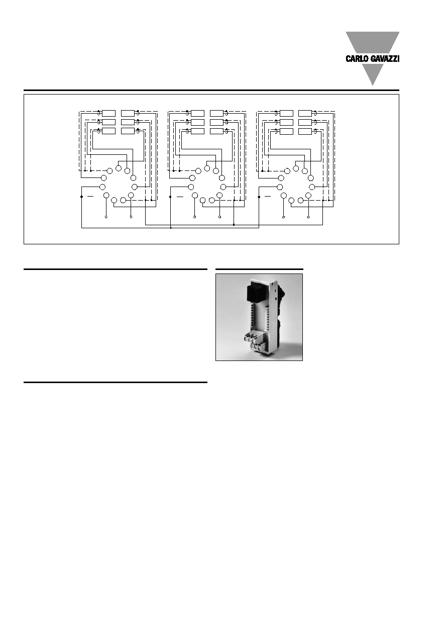
Wiring Diagram, Multiplex Mode
Power Supply
8
9
10
11
7
6
5
4
3
1
2
Rx 1
Rx 2
Rx 1
Rx 3
Tx 1
Tx 2
Rx 1
Tx 3
( )
Multiplex
Power Supply
8
9
10
11
7
6
5
4
3
1
2
Rx 1
Rx 2
Rx 1
Rx 3
Tx 1
Tx 2
Rx 1
Tx 3
( )
Multiplex
Power Supply
8
9
10
11
7
6
5
4
3
1
2
Rx 1
Rx 2
Rx 1
Rx 3
Tx 1
Tx 2
Rx 1
Tx 3
( )
Multiplex
Max. 3 amplifiers
S 1430 RAL
Accessories
- 11 pole circular socket
S111, S111A, S411, ZPD11
- Socket cover for S111
BB1
- Socket cover for S411
BB4
- Holding down spring
HF
- Mounting rack
SM13
- Front panel mounting bezel
FRS2
- Connection cable (2 plugs)
2 x 6/6 modular plugs
2.0 m, 6 wires two plugs
- Power supply for 115/230 VAC SS120-series
- DIN-rail interface
6IODC
Delivery Contents
∑
Output connection cable
1 m, 6 wires one plug
∑
Output connection cable
0.2 m, 6 wires two plugs
∑
Amplifier
S 1430 RAL 915
∑ DIN-rail interface
6IODC
∑ Screw driver
∑
Packaging:
Cardboard box
6IODC
DIN-rail interface
(DIN EN 50 035, EN 50 022)
Output from plug to screw
terminals
Interface