Specifications are subject to change without notice
1
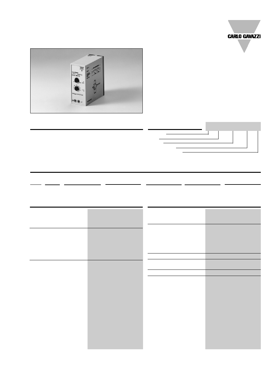
Current and Voltage Controls
3-Phase AC Max. Current Control
Type S 178
∑ Measuring ranges: 0.5-500 A
∑ 3-phase current metering relay for current
metering transformers, type MP 3...
∑ Knob-adjustable current level
∑ Built-in adjustable timer function
∑ Latching at set level possible
∑ Output: 10 A SPDT relay
∑ Plug-in type module
∑ S-housing
∑ LED-indication for output ON
∑ AC or DC power supply
Product Description
3-phase current metering
plug-in relay with adjustable
current value measured with
current transformer type MP...
Often used to prevent a motor
Ordering Key
Housing
Type
Output
Power supply
Measuring range
from overloading or from caus-
ing damage to equipment
working with a certain kind of
granulate. The S 178 features
built-in time delay.
Type Selection
Plug
Output
Measuring range
Supply: 24 VAC
Supply: 115 VAC
Supply: 230 VAC
Supply: 24 VDC
Circular SPDT
0.5 - 500 AAC
S 178 156 024 4V
S 178 156 115 4V
S 178 156 230 4V
S 178 156 724 4V
Input Specifications
Input
Pins 5 & 7
0.4 - 4V
p
, through current
transformer
Impedance
9.9 k
Measuring ranges
Types
Ranges
Max. current
AAC rms
rms
MP 3005
0.5 - 5
20 AAC
MP 3020
2 - 20
50 AAC
MP 3100
10 - 100
150 AAC
MP 3500
50 - 500
500 AAC
Latching
Interconnect pins 8 & 9
Output Specifications
Output
SPDT relay
Rated insulation voltage
250 VAC (rms)
(cont./elect.)
Contact ratings (AgCdO)
µ (micro gap)
Resistive loads
AC 1
10 A/250 VAC (2500 VA)
DC 1
1 A/250 VDC (250 W)
or
10 A/25 VDC (250 W)
Small inductive loads AC 15
2.5 A/230 VAC
DC 13
5 A/24 VDC
Mechanical life
30 x 10
6
operations
Electrical life
AC 1
2.5 x 10
5
operations
(at max. load)
Operating frequency
7200 operations/h
Dielectric strength
Dielectric voltage
2 kVAC (rms) (cont./elect.)
Rated impulse withstand volt. 4 kV (1.2/50 µs) (cont./elect.)
(IEC 60664)
S 178 156 024 4V
2
Specifications are subject to change without notice
Power supply AC types
Overvoltage cat. III (IEC 60664)
Rated operational voltage
(IEC 60038)
through pins 2 & 10
024
24 VAC ± 15%, 45 to 65 Hz
115
115 VAC ± 15%, 45 to 65 Hz
230
230 VAC ± 15%, 45 to 65 Hz
Voltage interruption
40 ms
Dielectric voltage
2 kVAC (rms) (supply/elect.)
Rated impulse withstand volt. 4 kV (1.2/50 µs) (line/neutral,
line/line), no direct connec-
tion to electronics
Power supply DC types
Overvoltage cat. III (IEC 60664)
Rated operational voltage
(IEC 60038)
through pins 2 & 10
724
24 VDC ± 15%
Dielectric voltage
None (supply/elect.)
Rated impulse withstand volt. 800 V (1.2/50 µs)
Rated operational power
AC supply
2.5 VA
DC supply
1.5 W
S 178
Hysteresis
10% ± 6%
Reaction time
Relay operates:
= 20 ms
Relay releases:
= 300 ms
worst case reaction time
may be up to 5 x
Adjustable delay on operate
built-in (0.2s - 10s)
Accuracy
ON delay
10 s, -1/+3 s on max.
< 0,1 s on min.
Indication for
Power supply ON
LED, green
Output ON
LED, red
Environment
(IEC 60947-1)
Degree of protection
IP 20 B (IEC 60529)
Pollution degree
2 (IEC 60664)
Operating temperature
-20∞ to +50∞C (-4∞ to +122∞F)
Storage temperature
-50∞ to +85∞C (-58∞ to +185∞F)
Weight
AC supply
200 g
DC supply
125 g
Approvals
UL, CSA
AC current metering
(example 1)
Carried out with the 3-phase
current metering transformer
type MP ... . This transformer
supplies an output voltage
between 0.4 and 4 V
p
, pro-
portional to the current flow
in a cable passing through
the holes in the transformer.
The relay operates when the
current in any of the phases
causes the input voltage on
pins 5 and 7 to reach set value.
The relay releases immediately
when the current in all 3 pha-
ses has dropped below set
value (see hysteresis) or when
power supply is interrupted.
Latching
(example 2)
The relay operates and latch-
es in operating position when
the current in any of the pha-
ses causes the input voltage
on pins 5 and 7 to reach set
value. The relay releases im-
mediately by removing the lat-
ch, i.e. by opening the contact
between pins 8 and 9, provi-
ded that the current in all 3
phases has dropped below
set value (see hysteresis), or
by interrupting power supply.
AC current metering
Hysteresis adjustment
(example 3)
As normal AC current meter-
ing except that the hysteresis
can be increased by an exter-
nal resistor mounted between
pins 8 and 9 (see Hysteresis
under Time/Range Setting).
Note:
At DC supply, do not connect
pins 7 and 10 as these pins
are internally connected by a
resistor of 3.9 k
. No current
must pass through this inter-
nal connection.
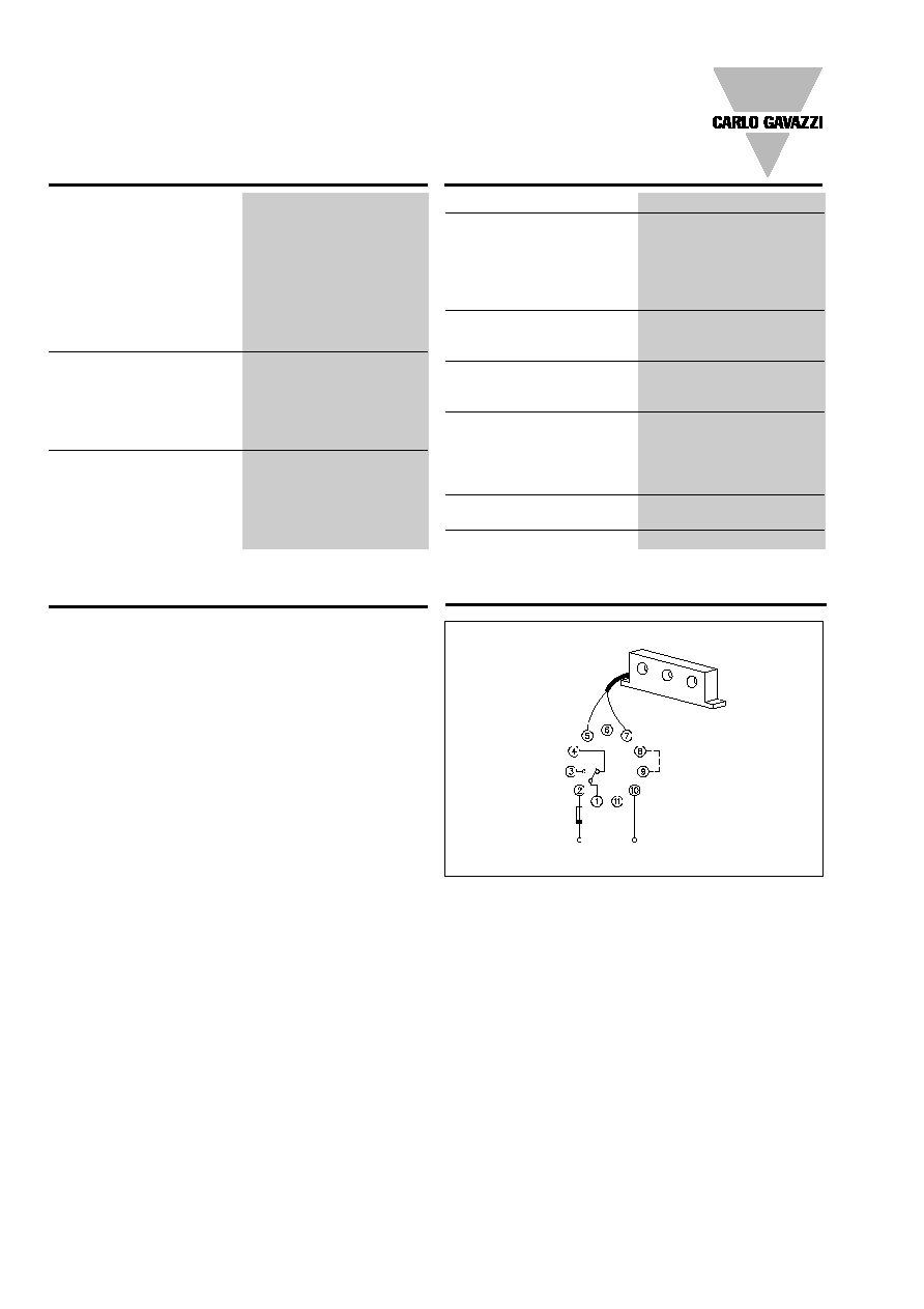
Mode of Operation
Wiring Diagram
S 178
Latching/
Hysteresis
black
Supply Specifications
General Specifications
PE = pin 7
(+)
(-)
Specifications are subject to change without notice
3
S 178
Sockets
S 411
Hold down spring
HF
Mounting rack
SM 13
Socket covers
BB 4
Front mounting bezel
FRS 2
Potentiometer lock
PL 2
Current metering transformers
MP 3005, MP 3020
MP 3100, MP 3500
For further information refer to "Current Metering Transfor-
mers" and "Accessories".
Accessories
Time/Range Setting
Time setting
Upper potentiometer:
Time setting on scale in sec-
onds.
Time range:
Delay on operate: 0.2 - 10s .
Range setting:
Lower potentiometer:
Adjustment of set point in
percent.
Hysteresis
10% ± 6%
The hysteresis may be ex-
tended to 75% by connect-
ing a resistor between pins
8 and 9. Resistor limits are
1 M
and 15 k
. The hystere-
sis is increased by decreasing
resistance.
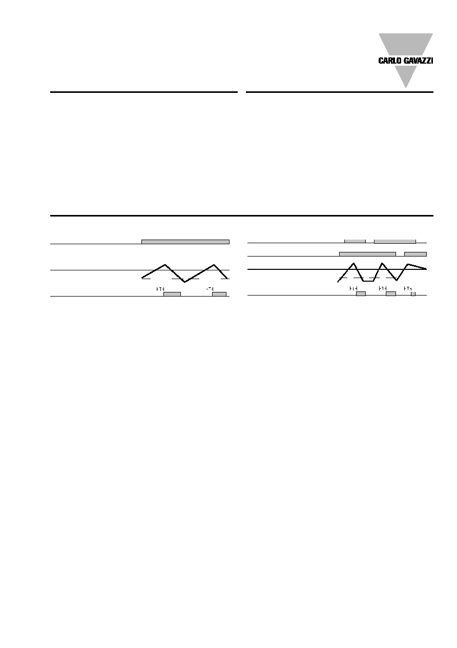
Operation Diagrams
Examples 1 og 3
Power supply
Set value
Input voltage
Example 2
Power supply
Latching
Set value
Input voltage
pins 5 & 7
Relay ON
pins 5 & 7
Relay ON
Hysteresis
Hysteresis