
Specifications are subject to change without notice (27.10.99)
1
Current and Voltage Controls
∑ 3-phase AC power metering and direction
relay
∑ For symmetrical loads
∑ Measures power up to 410 kW divided into 8 ranges
∑ Knob-adjustable power set point
∑ Built-in adjustable timer function
∑ Output: 10 A SPDT relay
∑ Plug-in type module
∑ S-housing
∑ LED-indication for power supply and output ON
∑ Power supply is the 3-phased measuring voltage
Product Description
3-phase power metering and
direction relay measuring the
effective power voltage direct-
ly and the current in one pha-
Ordering Key
Housing
Type
Output
Power supply
se with a transformer. Often
used for controlling 3-phase
motors or generators. Built-in
time delay.
Type Selection
Plug
Output
Supply: 220 VAC
Supply: 380 VAC
Supply: 400 VAC
Supply: 415 VAC
Circular
SPDT
S 1822 156 220
S 1822 156 380
S 1822 156 400
S 1822 156 415
Input Specifications
Input
Galvanical connection to elect.
Pins 8 & 11
0.4 - 4 V
p
from MI ... currrent trans-
former black wire connected
to pin 8 max. 20 V
Measuring ranges
Type
Voltage range
Trans- Current Power
(VAC)
former range(A) range (kW)
S 1822 156 220
190-250
MI 100 10-100
4.3 - 43
MI 500 50-500
22 - 216
S 1822 156 380
330-430
MI 100 10-100
7.4 - 74
MI 500 50-500
3.7 - 372
S 1822 156 400
340-460
MI 100 10-100
7.9 - 79
MI 500 50-500
40 - 398
S 1822 156 415
355-475
MI 100 10-100
8.2 - 82
MI 500 50-500
41 - 410
Output Specifications
Output
SPDT relay
Rated insulation voltage
250 VAC (rms)
(cont./elect.)
Contact rating (AgCdO)
µ (micro gap)
Resistive loads
AC 1
10 A/250 VAC (2500 VA)
DC 1
1 A/250 VDC (250 W)
or
10 A/25 VDC (250 W)
Small inductive loads AC 15
2.5 A/230 VAC
DC 13
5 A/24 VDC
Mechanical life
30 x 10
6
operations
Electrical life
AC 1
2.5 x 10
5
operations
(at max. load)
Operating frequency
7200 operations/h
Dielectric strength
Dielectric voltage
2 kVAC (rms) (cont./elect.)
Rated impulse withstand volt.
4 kV (1.2/50 µs) (cont./elect.)
(IEC 60664)
Instrument output
Pins 8 & 9, pins 9 pos.
Impedance
3.9 k
Moving-coil instrument
Connection with 1 mA
full scale deflection
Internal resistance
110
3-Phase Power Control
Type S 1822
S 1822 156 220
2
Specifications are subject to change without notice (27.10.99)
S 1822
Power supply AC types
Overvoltage cat. III (IEC 60664)
Rated operational voltage
(IEC 60038)
Through pins 5, 6 & 7
220
220 VAC ± 15%, 45 to 65 Hz
380
380 VAC ± 15%, 45 to 65 Hz
400
400 VAC ± 15%, 45 to 65 Hz
415
415 VAC ± 15%, 45 to 65 Hz
Voltage interruption
40ms
Dielectric voltage
None (supply/elect.)
Rated impulse withstand volt.
4 kV (1.2/50 µs) (line/neutral,
line/line), direct connection
to electronics
Rated operational power
2.5 VA
Hysteresis
Typically 10%
Reaction time
= 60 ms, worst case reaction
time may be up to 5 x
Indication for
Power supply ON
LED, green
Output ON
LED, red
Environment
(IEC 60947-1)
Degree of protection
IP 20 B (IEC 60529)
Pollution degree
(IEC 60664)
1: S 1822 380/400/415
2: S 1822 220,
Operating temperature
-20∞ to +50∞C (-4∞ to +122∞F)
Storage temperature
-50∞ to +85∞C (-58∞ to +185∞F)
Weight
200 g
Approval
UL, CSA
S 1822 is suitable for control-
ling 3-phased motors or gen-
erators.
The relay measures the ef-
fective power:
P =
3 x U x I x cos
, by
measuring the phase voltage
through pins 5, 6 and 7. The
phase sequence is arbitrary.
The current is measured in 1
phase by current metering
transformer type MI... If in-
creased sensitivity is re-
quired, the metered cable
Mode of Operation
can be put through the cur-
rent transformer several times.
S 1822 measures the power
in one phase; at symmetrical
loads this phase is represen-
tative of all 3 phases.
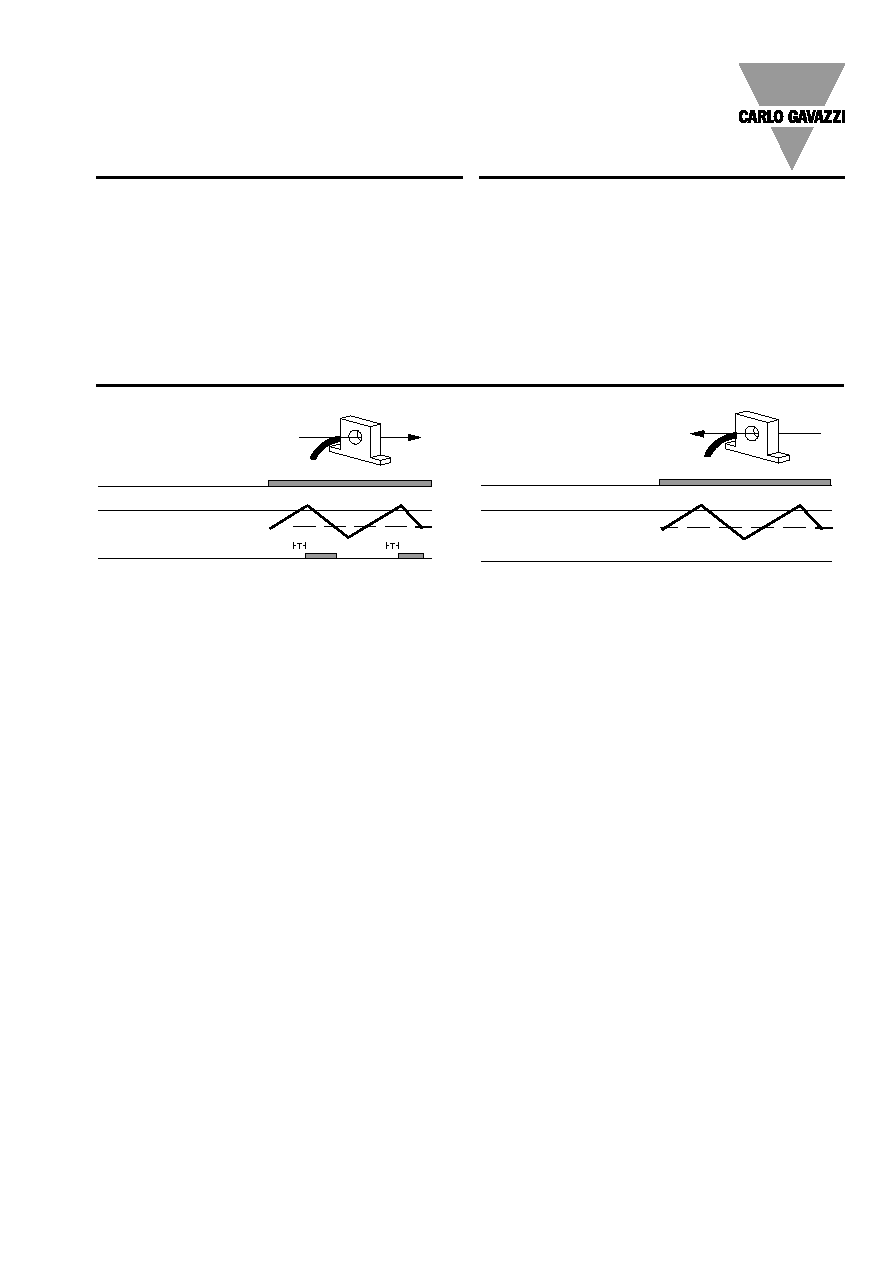
When registered effective po-
wer exceeds the set power
limits, the relay operates with
a delay of 0.2 - 10 sec.
The relay releases immedi-
ately when the measured ef-
fective power drops below set
value less hysteresis. The
measured effective power can
be read on the connected in-
strument.
At wrong direction, the instru-
ment displays zero.
Due to the detection of direc-
tion and the time constant,
the relays are also suitable in
connection with the decoup-
ling of windmill generators.
The relay is also suitable
where reading on an instru-
ment as well as monitoring of
consumed power are re-
quired. S 1822 is applicable
for controlling mechanical
loads because it takes into
consideration changes in cur-
rent as well as in cos
.
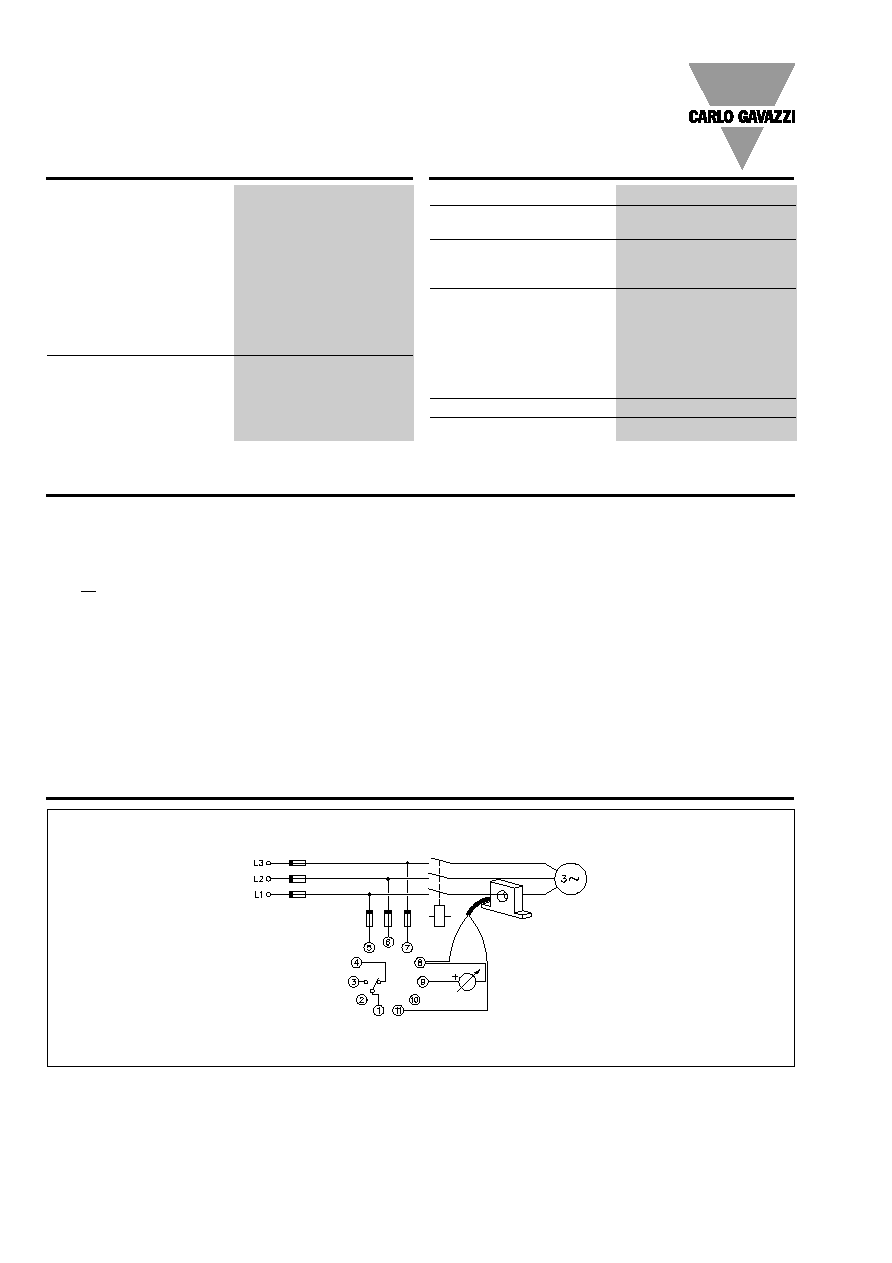
Note: Internal measuring cir-
cuit is connected to pins 5 &
6.
All pins except for the relay
contacts have the potential
of the power supply, this ap-
plies to the instrument as well.
Wiring Diagram
S 1822
Motor/generator
black
Supply Specifications
General Specifications
Specifications are subject to change without notice (27.10.99)
3
S 1822
Sockets
S 411
Hold down spring
HF
Mounting rack
SM 13
Socket covers
BB 4
Front mounting bezel
FRS 2
Potentiometer lock
PL 2
Current metering transformers MI 100, MI 500
For further information refer to "Current Metering Transfor-
mers" and "Accessories".
Accessories
Time/Range Setting
Time setting
Upper potentiometer:
Delay on operate:
0.2 to 10 s (tolerance on max.:
-1 s, +3 s).
Range setting:
Lower potentiometer:
Set point on scale from 10 to
100%.
Hysteresis
Approx. 10% in the upper range
and approx. 30% in the lower
range.
Operation Diagrams
Power supply
Power supply
Set value
Hysteresis
Eff. power
Relay ON
Set value
Hysteresis
Eff. power
Relay ON