
Specifications are subject to change without notice (25.06.99)
1
Level Sensors
Type S 1961
∑ Level control for conductive liquids
∑ Max.- min. control of charging/discharging
∑ Selection of charging or discharging by inter-
connection of the pins
∑ 3 sensitivity ranges, from 200
to 220 k
,
selectable by switch in the front
∑ Adjustable sensitivity
∑ Possibility of parallel connection
∑ Level probe supply max. 6 V
pp
, 1.5 mA, according
to IEC 60364-4-41, FELV
∑ Output: 10 A SPDT relay
∑ LED-indication for relay and power supply ON
∑ AC or DC power supply
Product Description
Level control relay for conduc-
tive liquids which can control
two levels of charging or dis-
charging. The relay features
sensitivity ranges from 200
to 220 k
(5 m Siemens to 4.5 µ
Siemens). If more than two
levels are required, more re-
lays can be cascaded.
Ordering Key
Housing
Type/function
Output
Power supply
Type Selection
Plug
Output
Supply: 24 VAC
Supply: 115 VAC
Supply: 230 VAC
Supply: 24 VDC
Circular
SPDT
S 1961 156 024
S 1961 156 115
S 1961 156 230
S 1961 156 724
Input Specifications
Level probe supply
6 V
pp
(IEC 60364-4-41, FELV)
Level probe current
Range 1: 200
- 2.2 k
1.5 mA
Range 2: 2.0 k
- 22 k
150 µA
Range 3: 20 k
- 220 k
15 µA
Clock in/clock out
Clock in: pin 9
Clock out: pin 8
Approx. 100 Hz ±15 Hz
square wave
Duty cycle typically 60-40
For cascading of more
amplifiers
Always use screened cable
to avoid ambient noise
Screen must be connected
to pin 7
Reaction time
Approx. 1 s
Output Specifications
Output
SPDT relay
Rated insulation voltage
250 VAC (rms) (cont./elect.)
Contact ratings (Ag-CdO)
(IEC 60947-5-1/IEC 60337)
Resistive loads
AC 1
10 A/250 VAC (2500 VA)
DC 1
1 A/250 VDC (250 VA)
or
10 A/25 VDC (250 VA)
Small inductive loads AC 15
2.5 A/230 VAC
DC 13
5 A/24 VDC
Mechanical life
30 x 10
6
operations
Electrical life
AC 1
2.5 x 10
5
operations
(at max. load)
Operating frequency
7200 operations/h
Insulation voltages
Rated insulation voltage
2.0 kVAC (rms)
(cont./elect.)
Rated impulse withstand
voltage
4 kV (1.2/50 µs)
(cont./elect.) (IEC 60664)
Charging or Discharging
S 1961 156 230
2
Specifications are subject to change without notice (25.06.99)
Supply Specifications
Power supply AC types
Overvoltage cat. III (IEC 60664)
Rated operational voltage
through pins 2 & 10
230
230 VAC ±15%,
50/60 Hz, -5/+5 Hz
115
115 VAC ±15%
50/60 Hz, -5/+5 Hz
024
24 VAC ±15%
50/60 Hz, -5/+5 Hz
Voltage interruption
40 ms
Rated insulation voltage
2.0 kVAC (rms)
Rated impulse withstand
voltage
4 kV (1.2/50 µs) (line/neutral)
Power supply DC type
Overvoltage cat. III (IEC 60664)
Rated operational volt. 724
24 VDC ±15% (pin 2 pos.)
Rated insulation voltage
None
Rated impulse withstand
voltage
800 V (1.2/50 µs) (line/neutral)
Rated operational power
AC supply
2.5 VA
DC supply
1.5 W
General Specifications
Indication for
Power supply ON
LED, green
Output ON
LED, red
Environment
Degree of protection
IP 20 B
Pollution degree
2 (IEC 60664)
Operating temperature
-20∞ to +50∞C (-4∞ to +122∞F)
Storage temperature
-50∞ to +85∞C (-58∞ to +185∞F)
Scale accuracy
+/- 20%
Hysteresis
100% of set value
Weight
AC-Types
200 g
DC-Type
125 g
Approvals
UL, CSA
CE-marking
Yes
S 1961
Mode of Operation
Max., min. control of char-
ging/discharging.
Example 1
The diagram shows the level
control connected as max.
and min. control, i.e. detection
of 2 levels. The relay operates
(out)/releases (in) when the
liquid reaches the max. elec-
trode (pin 5), provided that the
min. electrode (pin 6) is in
contact with the liquid.
The relay releases (out)/ope-
rates (in) when the min. elec-
trode is no longer in contact
with the liquid.
By use of a container of a
conductive material pin 7 can
be connected to the contain-
er. If the container is made of
a non-conductive material, an
additional electrode is need-
ed, indicated by the dotted
line in the diagram.
If only one level is required,
pins 5 and 6 must be inter-
connected, to select either
max. or min. control.
Example 2
If more than 2 levels are re-
quired, two or more amplifiers
can be cascaded, as shown
in example 2.
Pin 8 (clock out) and pin 9
(clock in) are connected to
synchronize the clock in all
systems - otherwise interfe-
rence may occur. This means
that one system determines
the clock for all systems cas-
caded.
The clock in/clock out con-
nection must be screened ca-
ble. In some cases screened
cable must be used to achieve
perfect operation, e.g. in cable
pits or trays where the sensor
cable is close to power cab-
les. Connect the screen to pin
7.
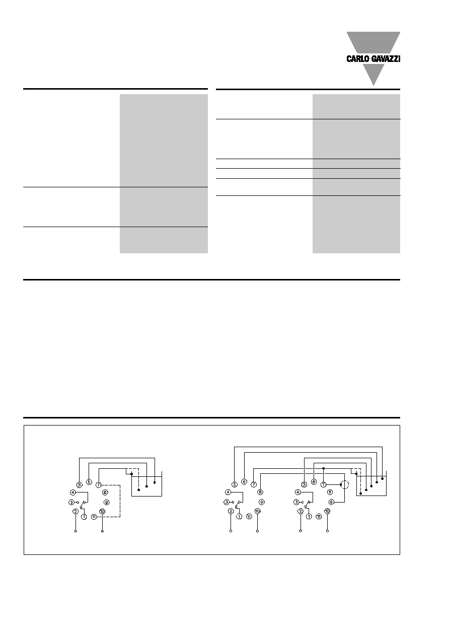
Wiring Diagrams
Example 1
Example 2
Min.
Max.
Clock out
Clock in
Power supply
Power supply
Power supply
PE=Pin 7
8: Clock out
9: Clock in
7-11: Charge

Specifications are subject to change without notice (25.06.99)
3
S 1961
Accessories
Settings
Conductive level probes:
VN..., VNI..., VNY..., VNYI..., VT..., VTI..., VPP..., VPC..., VH...
Socket
S 411
Hold down spring
HF
Mounting rack
SM 13
Socket cover
BB 4
Front mounting bezel
FRS 2
Upper knob: Sensitivity
Lower knob: Range selection
Operation Diagram
Power supply
Max.
Min.
Relay (charging: in)
Relay (discharging: out)