
Specifications are subject to change without notice (25.06.99)
1
Level Sensors
∑ Controller for conductive liquids
∑ Controls minimum/maximum and indicates over and
under alarm
∑ Filling or emptying function selectable
∑ Fixed sentitivity
∑ 2 x 5 A 250 VAC relay outputs, SPST
∑ 4 LED indications: Pump running, power supply ON,
alarm high (HiHi) and alarm low (LoLo)
∑ AC power supply: 24 VAC, 115 VAC and 230 VAC
Product Description
Ordering Key
S 197 256 024
Level control relay for con-
ductive liquids. Unit features
output for controlling high
and low levels as well as
separate output for alarm
indication in case of tank
running dry or an overflow
condition.
Housing
Type/function
Output configuration
Power supply
Type Selection
Plug
Supply: 24 VAC
Supply: 115 VAC
Supply: 230 VAC
11-pin circular
S 197 256 024
S 197 256 115
S 197 256 230
Note: There is approximately a 2 seconds delay on the output to compensate for wave action.
Input Specifications
Level probe supply
Max. 12 VAC
Level probe current
Max. 2.5 mA
Sensitivity
ON (pin 5-6 and 7)
< 25 k
(approx.)
OFF (pin 5-6 and 7)
> 35 k
(approx.)
Type S 197 (Charging/Discharging)
Amplifier, Conductive
Supply Specifications
Power supply
Overvoltage cat. II (IEC 60664)
Rated operational voltage
through pin 2 & 10
230
230 VAC ± 15%
115
115 VAC ± 15%
024
24 VAC ± 15%
Rated insulation voltage
2.0 kVAC (rms)
Rated impulse withstand
voltage
4 kV (1.2/50 µs)
(line/neutral)
General Specifications
Indication for
Power supply ON
LED, green
Output ON
LED, yellow
Alarm HiHi
LED, red
Alarm LoLo
LED, red
Environment
Degree of protection
IP 20 B
Pollution degree
3 (IEC 60664)
Operating temperature
-20∞ to +50∞C (-4∞ to +122∞F)
Storage temperature
-50∞ to +85∞C (-58∞ to +185∞F)
CE-marking
Yes
Output Specifications
Output
SPST relay
Rated insulation voltage
250 VAC (rms) (cont./elec.)
Contact ratings (AgCd0)
µ (micro gap)
Resistive loads
AC 1
5 A/250 VAC (2500 VA)
DC 1
1 A/250 VDC (250 W)
or
5 A/25 VDC (250 W)
Small inductive loads AC 15
2.5 A/230 VAC
DC 13
5 A/24 VDC
Mechanical life
30 x 10
6
operations
Electrical life
AC 1
2.5 x 10
5
operations
(at max. load)
Operating frequency
7200 operations/h
Insulation voltages
Rated insulation voltage
2.0 kVAC (rms)
(cont./elec.)
Rated transient protection volt. 4 kV (1.2/50 µs)
(cont./elec.) (IEC 60664)
2
Specifications are subject to change without notice (25.06.99)
A ccessories
Conductive level probes:
VH
VPC, VPP
VN, VNY, VNI
VT, VTI
VS
Base
S 411
Hold down spring
HF
Base cover
BB 4
Front mounting bezel
FRS 2
Operation Diagrams
Mode of Operation
The switch at the front is set in
the desired mode IN (charging)
or OUT (discharging).
Connection cable
2 or 3 core PVC cable, normally
unscreened. Cable length:
max. 100 m. The resistance
between the cores and the
ground must be at least 220
k
. In certain cases it is rec-
ommended to use screened
cable between sensor and
amplifier, e.g. where the cable
is placed in parallel to the
load cables (mains). The
screen is connected to pin 7.
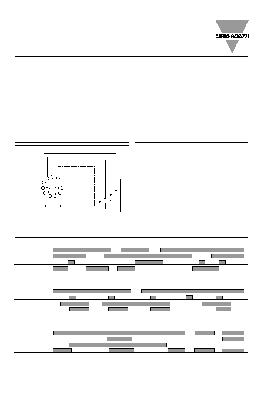
Example 1
The diagram shows the level
control connected as max. and
min. control, i.e. registration
of 2 levels. The relay opera-
tes (OUT)/releases (IN) when
the liquid reaches the Hi
electrode (pin 5), provided
that the Lo electrode (pin 6)
is in contact with the liquid.
The relay releases (OUT)/-
operates (IN) when the Lo
electrode is no longer in
contact with the liquid. Pin 7
must be connected to the
container. If the container
consists of a non-conduc-
tive material, an additional
electrode must be used. (To
be connected to pin 7. In the
diagram this electrode is
shown by the dotted line.)
The alarm outputs utilise
electrodes on pin 4 for HiHi
alarm and pin 8 for LoLo
alarm. Because alarm condi-
tions of HiHi and LoLo can
not be experienced at the
same time the LED indica-
tion on the front of the hous-
ing offers visual confirmation
as to which alarm condition
is active or present.
Wiring Diagram
Power Supply
8
9
10
11
7
6
5
4
3
1
2
Pump on/off
Alarm on/off
HiHi
Hi
Lo
LoLo
GND
2sec
2sec
OFF
ON
OFF
ON
Front selectable
Example 1
S 197
Power supply
Power supply
Power supply
Lo electrode (pin 6) in liquid
Hi electrode (pin 5) in liquid
Relay on pumping contact 1
Hi electrode (pin 5) in liquid
Lo electrode (pin 6) in liquid
Relay on pumping contact 1
HiHi electrode (pin 4) in liquid
LoLo electrode (pin 8) in liquid
Relay on alarm contact 2
(Charging contact no. 1. pumping) ON-OFF
(Discharging contact no. 1. pumping) OFF-ON
(Alarm contact no. 2. High or low)
LED Lo Alarm
LED Hi Alarm
LED Lo Alarm
LED Lo Alarm
LED Lo & Hi Alarm