 | –≠–ª–µ–∫—Ç—Ä–æ–Ω–Ω—ã–π –∫–æ–º–ø–æ–Ω–µ–Ω—Ç: SPD244801 | –°–∫–∞—á–∞—Ç—å:  PDF PDF  ZIP ZIP |
Specifications are subject to change without notice
1
∑ Universal AC single phase input full range
∑ Installation on DIN rail 7.5 or 15mm
∑ PFC as standard
∑ High efficiency up to 90%
∑ Power ready output
∑ Parallel connection feature
∑ Compact dimensions
∑ UL, cUL listed and TUV/CE approved
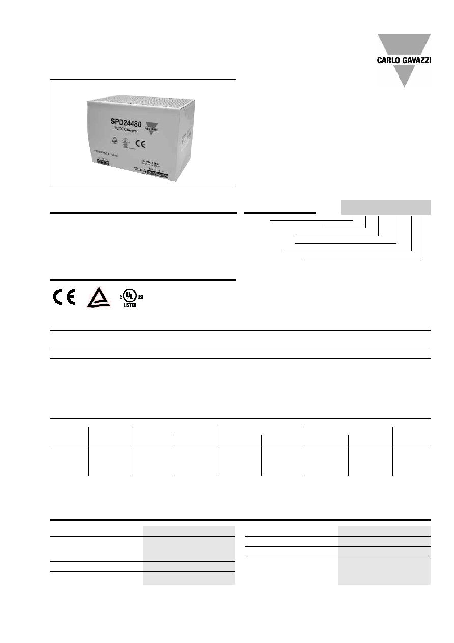
Product Description
The Switching power
supplies SPD series are
specially designed to be
used in all automation
application where the
installation is on a DIN rail
and compact dimensions
and performance are a must.
Switching Power Supply
Type SPD 480W
DIN rail mounting
Optional Features
Approvals
Description
code
Plug-in connectors
B
Line regulation
± 0.5%
Load regulation
Non parallel mode
± 0.5%
Parallel mode
± 5%
Ouput Voltage accuracy
+1% (factory adjusted)
Ripple and Noise
100mV
Temperature Coefficient
+0,02% / ∞C
Hold up time Vi = 230Vac
30ms
Minimum load
0%
Parallel Operation
3 units max.
(only with S/P switch
on "P" position)
Output data
Model
Mounting ( D = Din rail )
Output voltage
Output power
Input Type
Optional features
Input type: 1= single phase
Ordering Key
SP D 24 480 1 B
Output performances
Model
SPD24
SPD48
Output
Current (A)
20
10
Min. VDC
22.5
47.0
Max. VDC
28.5
56.0
Min.
17.6
37.0
Max.
19.4
40.0
Min.
17.6
37.0
Max.
19.4
40.0
Typical
Efficiency
89%
90%
Voltage Trim Range
1)
DC OK @ Start up (VDC)
Dc low after start up (VDC)
1)
When S/P switch is set to parallel, it is not possible to trim output voltage.
2
Specifications are subject to change without notice
Switching Power Supply
Type SPD 480W
DIN rail mounting
Input Fuse
T10A/250Vac internal*
Overvoltage Protection SPD24
30 ≠ 33VDC
SPD48
57 ≠ 63VDC
Output Short Circuit
Current limit
Rated Overload Protection
120-140%
Power ready output
(only SPD 24)
Threshold voltages
17.6 - 19.4 VDC
Contact rating at 60Vdc
0.3A
insulation
500Vdc
Controls and Protections
Ambient temperature
-25∞C to 71∞C
Derating (>56∞C to +71∞C)
2.5%/∞C
Ambient humidity
20 - 95%RH
Storage
-25∞C to +85∞C
Dimensions L x W x D
Screw terminal type
125 x 175 x 123
Plug in connectors
142 x 175 x 123
Cooling
Free air convection
MTBF (MIL-HDBK-217F)
n.a.
Case material
Metal (powder painted aluminium)
Weight
1920g
Protection degree
IP20
General data (@ nominal line, full load, 25∞C )
Insulation voltage I/O
3.000Vac
Insulation resistance I/O
@ 500VDC
100Mohm
UL / cUL
UL508 listed, UL60950-1,
Recognised
TUV
EN60950-1
CE
EN61000-6-3
EN55022 class B
EN61000-3-2
EN61000-3-3
EN61000-6-2
EN55024
Approvals and EMC
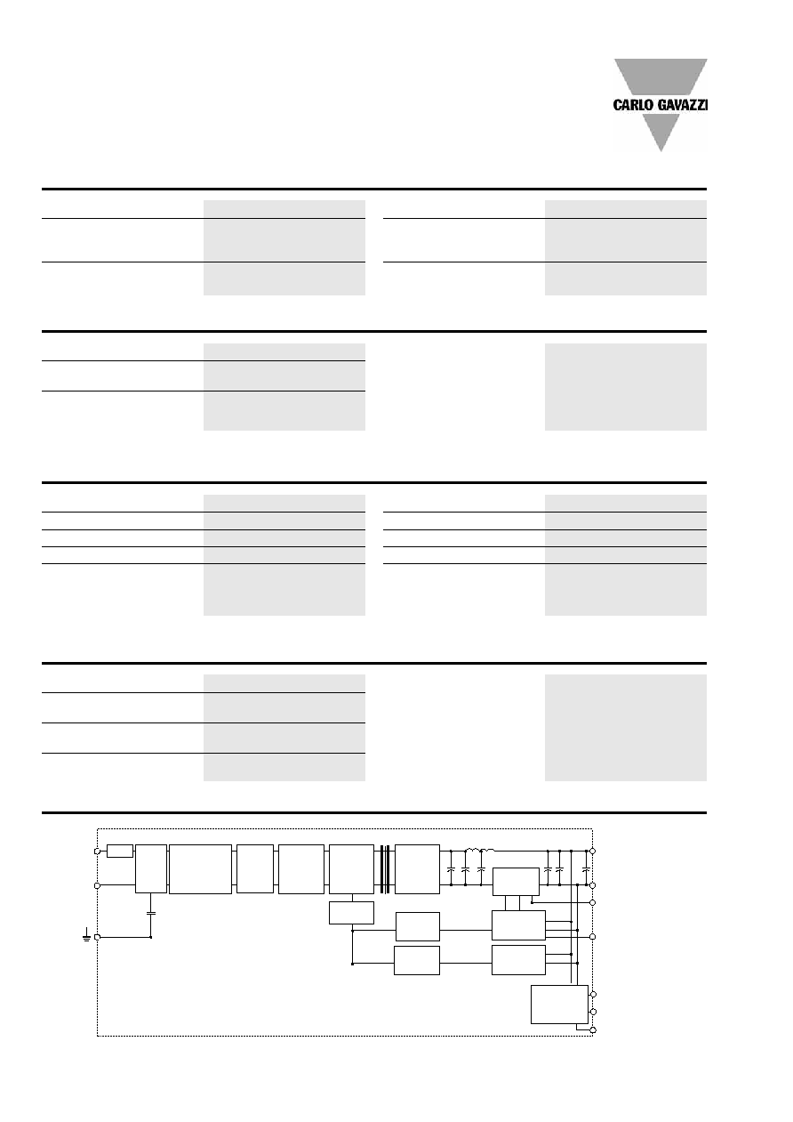
Block diagrams
L
N
Y
Vo +
Vo -
Vout
ADJ.
Single/Parallel
Select
DCON
(Green LED)
DCLOW
(Red LED)
RDY 1)
(Relay Contact)
Fuse
Line
Filter
P.F.C.
Circuit
Inrush Current
Limiter and
Rectifier
Switching
Device
Smoothing
Circuit
Rectifier
PWM
Controller
Current
Detection
Opto -
isolation
Opto -
isolation
Reference &
Error Amp.
Over Voltage
Detection
Output Level
Detection
1) For 24V only
Rated input voltage
115/264VAC
Voltage range
AC in
90 - 264 Vac
DC in
120 - 370 Vdc
Rated input current (115/230)
7 / 3.5A
Frequency range
47- 63 Hz
Inrush current
Vi= 115Vac
25A
Vi= 230Vac
50A
P.F.C. Vi= 230Vac, Ionom.
0.99
Input data
* Not replaceable by user.
SPD 24
Specifications are subject to change without notice
3
Switching Power Supply
Type SPD 480W
DIN rail mounting
Installation
VENTILATION / COOLING:
∑ Normal air convection
∑ 25mm of free space along all sides to allow good
cooling
SCREW CONNECTIONS:
∑ 10-24AWG Flexible or solid cable. 8mm stripping
recommended
PLUG IN CONNECTORS:
∑ 10-24AWG Flexible or solid cable. 7mm stripping
recommended
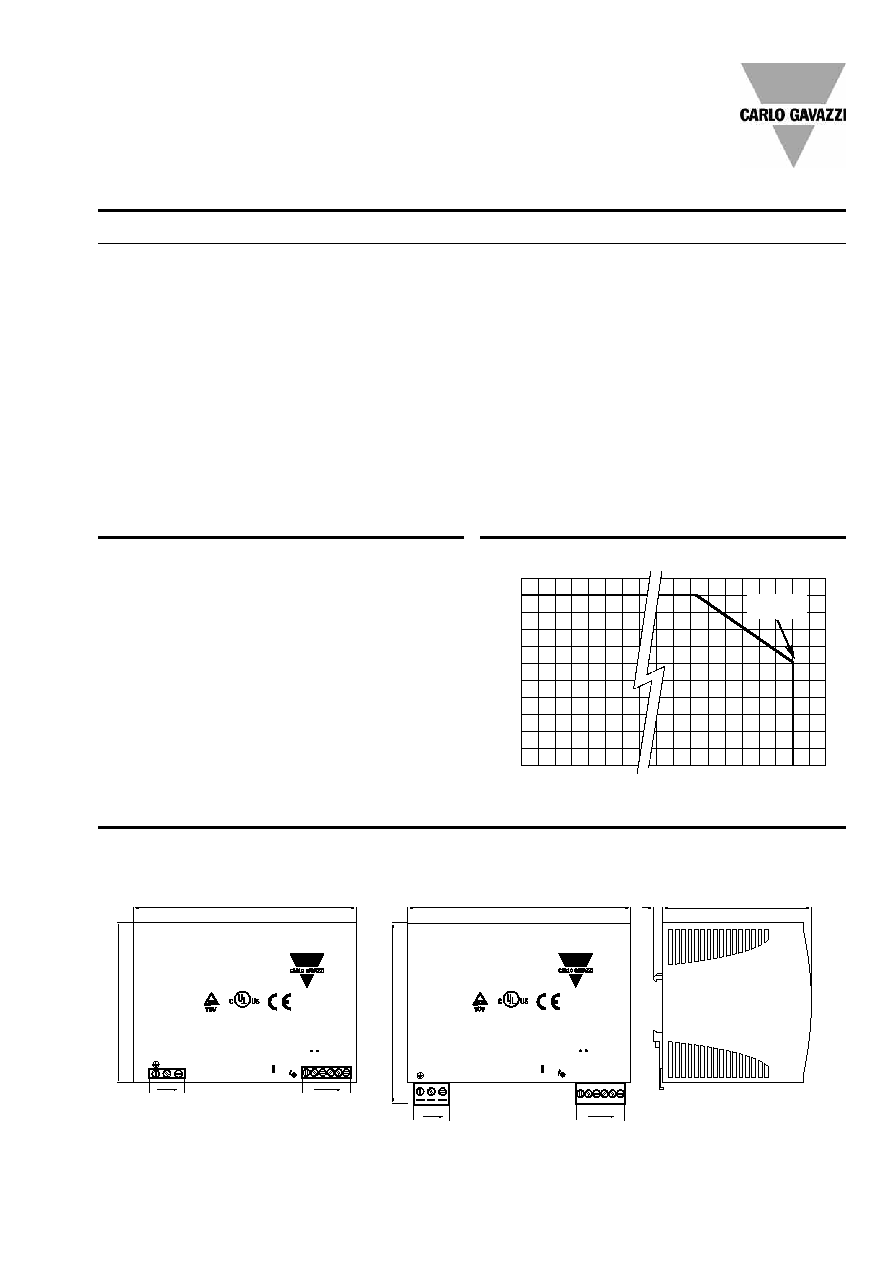
Derating Diagram
Power out (%)
Temperature (∞C)
100
90
80
70
60
50
40
30
20
10
0
-10
0
5
10
50
55
60 65
70
75
Mechanical Drawings
SPD24480B
AC/DC Converter
115/230VAC 47-63Hz
N L
24VDC / 20A
DC LO
DC ON
Rdy + + - -
parallel -
single -
Vout Adj
SPD24480
AC/DC Converter
115/230VAC 47-63Hz
N L
24VDC / 20A
DC LO
DC ON
Rdy + + - -
parallel -
single -
Vout Adj
Pin No.
Designation
Description
1
RDY (only SPD 24)
DC OK, relay normally open contact
2
RDY (only SPD 24)
DC OK, relay normally open contact
3
+
Positive output terminal
4
+
Positive output terminal
5
-
Negative output terminal
6
-
Negative output terminal
7
GND
Ground terminal to minimise High frequency emissions
8
L
Phase input ( no polarity with DC input )
9
N
Neutral input ( no polarity with DC input )
DC ON
DC output ready LED
DC LO
DC low indicator LED
Vout ADJ.
Trimmer for fine output voltage adjustment
S/P
Single parallel selection switch
Pin assignement and front controls
175
175
116
1
2
5
1
4
2
7
9
7
9
1
6
1
6
7
Power out
62.5%