Specifications are subject to change without notice
1
∑
16-bits µP-based smart power transducer
∑
Measurements of: W, Wavg, VA, VAr, PF, Wh, VAh, VArh,
Amax (among the phases), V
L
-
L
avg, VL1-N, VL2-N,
VL3-N, Hz L1.
∑
TRMS measurement of distorted waves (voltage/current)
∑
All configuration functions selectable by
built-in key-pad
∑
Password protection of programming parameters
∑
Degree of protection (front): IP 50
∑
Optional independent alarm setpoint
∑
Optional analogue output (20 mA DC/±10 mA DC/
±5 mA DC/10 VDC/±1VDC)
∑
Optional serial RS 422/485 output
∑
MODBUS, JBUS protocol.
Product Description
Model
Range code
System
Power supply
Auxiliary output
1st output/input
2nd output
Ordering Key
SPT-DINAV51D X A X
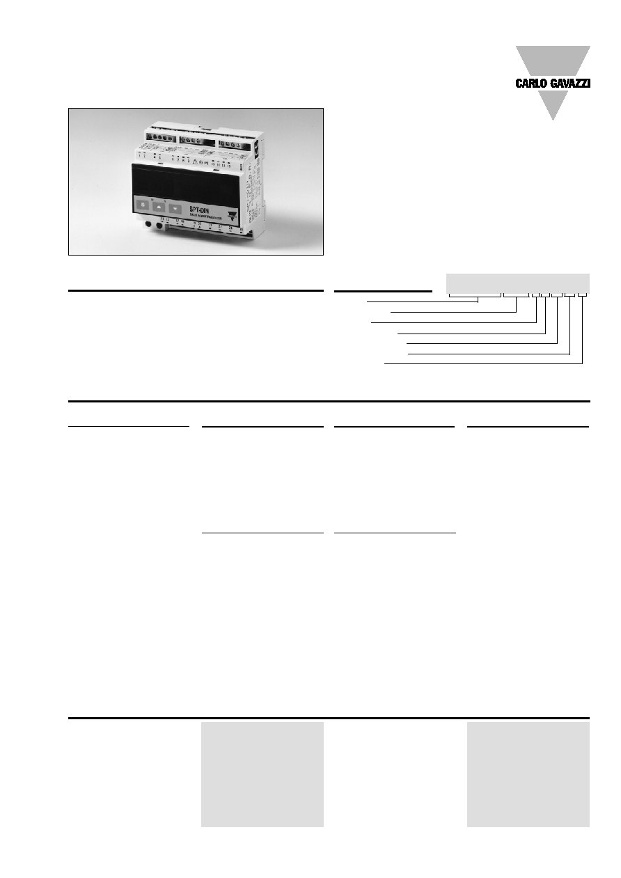
16-bit µP-based smart power
transducer with a built-in
configuration key-pad. The
house is for DIN-rail mounting
and ensures a degree of
protection (front) of IP 50.
Energy Management
Smart Power Transducer
Type SPT-DIN
Type Selection
System
1:
One phase, three-
phase system
(3 or 4 wires, balan-
ced load)
3:
Three phase system
(3 or 4 wires, unba-
lanced load)
Range code
AV1:
100/
3/100 VAC-1 AAC
(max. 130/
3 (L-N)/
130 V (L-L) - 1.2 A)
1)
AV3:
100/
3/100 VAC-5 AAC
(max. 130/
3 (L-N)/
130 V (L-L) - 6 A)
1)
AV4:
250/433 VAC - 1 AAC
(max. 300 V (L-N)/
520 V (L-L) - 1.2 A)
1)
AV5:
250/433 VAC - 5 AAC
(max. 300 V (L-N)/
520 V (L-L) - 6 A)
(standard)
Power supply
A:
24 VAC, -15% +10%,
50/60 Hz
1)
B:
48 VAC, -15% +10%,
50/60 Hz
1)
C:
115 VAC, -15% +10%,
50/60 Hz
1)
D:
230 VAC, -15% +10%,
50/60 Hz (standard)
Auxiliary output
X:
No output (standard)
D:
Alarm set-point, static,
AC type
1)
P:
Pulse, static,
DC type
1)
1st output/input
D:
3 digital inputs
(managed only by
means of the serial
communication)
1)
A:
Analogue output,
20 mADC (standard)
B:
Analogue output,
±10 mA
1)
C:
Analogue output,
±5 mA
1)
V:
Analogue output,
10 VDC
1)
U:
Analogue output,
0 to ±1 VDC
1)
2nd output
X:
No output (standard)
S:
Serial output, RS 485
multidrop bidirec-
tional
1)
A:
Analogue output,
20 mADC
1)
B:
Analogue output,
±10 mA
1)
C:
Analogue output,
±5 mA
1)
V:
Analogue output,
10 VDC
1)
U:
Analogue output,
0 to ±1 VDC
1)
Note: Only for B and C out-
puts, the 2nd output can
only be a B, C or S one.
Number of inputs
Current
2 (system code: 1)
6 (system code: 3)
Voltage
2 (system code: 1)
4 (system code: 3)
Digital
4, for 3 free of voltage con-
tacts (inputs managed only
by the serial communication)
Reading voltage/current:
24 VDC/1 mA
Accuracy
Voltage/current/energy
±0.5% f.s. includes also:
frequency, power supply
and output load influences
Frequency
±0.5% f.s. (45 to 500 Hz)
Active power
(@ 25∞C ± 5∞C, R.H.
60%)
±0.5% f.s. (PF 0.7 L/C,
0.6 to 1 In, 0.9 to 1.1 Un)
±1% f.s. (PF 0.3 L/C,
0.2 to 1.2 In, 0.7 to 1.2 Un)
Input Specifications
1)
On request
2
Specifications are subject to change without notice
SPT-DIN
Analogue outputs
Number of outputs
1 (standard) + 1 (on request)
Range
0 to 20 mADC,
0 to ±10 mADC,
0 to ±5 mADC,
0 to 10 VDC,
0 to ± 1 VDC
Scaling factor
Programmable within the
whole range of retransmis-
sion; it allows the retrans-
mission management of all
values from
0 to 20 mA,
0 to ±10 mADC,
0 to ±5 mADC
0 to 10 V,
0 to ± 1 VDC
Response time
250 ms typical
(filter excluded)
Temperature drift
300 ppm/∞C
Load:
20 mA output
500
±10 mA output
500
±5 mA output
1000
10 V output
10 k
± 1 V output
10 k
Insulation
By means of optocouplers,
2000 V
rms
output to
measuring input
4000 V
rms
output to
supply input
Serial output (on request)
Type
RS422/RS485;
Multidrop
bidirectional (static and
dynamic variables)
Connections
4 wires, max. distance
1200m, termination and/or
line bias by means of DIP-
switches directly on the
transducer
Addresses
255, selectable by key-pad
Protocol
MODBUS/JBUS
Data (bidirectional)
Dynamic (reading only)
System variables:
P, P
AVG
, S, Q, PF, V
L-L
, f,
energy and status of digital
inputs, setpoint output and
status of the energy over-
flow bit,
Single phase variables:
P
L1
, S
L1
, Q
L1,
PF
L1
, V
L1-N
, A
L1
,
P
L2
, S
L2,
Q
L2
, PF
L2
, V
L2-N
, A
L2
,
P
L3
, S
L3,
Q
L3
, PF
L3
, V
L3-N
, A
L3
Static (writing only)
All programming data, reset
of energy, reset of energy
overflow bit, activation of
static output.
Stored energy (EEPROM)
250,000.000 kWh
Data format
1-start bit, 8-data bit, no
parity/even parity, 1 stop bit
Output Specifications
Accuracy (cont.)
Reactive power
(@ 25∞C ± 5∞C, R.H.
60%)
±0.5% f.s. (PF 0.7 L/C,
0.6 to 1 In, 0.9 to 1.1 Un)
±1% f.s. (PF 0.3 L/C,
0.2 to 1.2 In, 0.7 to 1.2 Un)
Apparent power
(@ 25∞C ± 5∞C, R.H.
60%)
±0.5% f.s.,
(0.6 to 1 In, 0.9 to 1.1 Un)
±1% f.s.,
(0.2 to 1.2 In, 0.7 to 1.2 Un)
Additional errors
Humidity
< 0.3%, 60% to 90% R.H.
Input frequency
< 0.4%, 62 to 400 Hz
Magnetic field
< 0.5% @ 400 A/m
Ripple
1% according to IEC 60688-1
and EN 60688-1
Sampling rate
1900 Hz
Display
7-segment, LED, h 14.2 mm
Max. and min. indication
Max. 999, min. -999
Measurements
W, Wavg, VA, VAr, PF, Wh,
VAh, VArh, Imax (among the
phases), Vdelta avg, VL1-N,
VL2-N, VL3-N, Hz L1.
TRMS measurement of a dis-
torted wave voltage/current
Coupling type : Direct
Crest factor:
3
Ranges (impedances)
AV1 (Un/In):
100 V /
3/100 V (250 k
) -
1 AAC (
0.3 VA)
AV3 (Un/In):
100 V /
3/100 V (250 k
) -
5 AAC (
0.3 VA)
AV4 (Un/In):
250 V/433 V (1 M
) -
1 AAC (
0.3 VA)
AV5 (Un/In):
250 V/433 V (1 M
) -
5 AAC (
0.3 VA)
Frequency range
48 to 62 Hz
Over-load protection
Continuous: voltage/current
1.2 x rated input
For 1 s
Voltage:
2 x rated input
Current:
20 x rated input
Keyboard
3 keys:
"S" for enter programming
phase and password confir-
mation,
"UP" and "DOWN" for
value programming/function
selection
Input Specifications (cont.)

Specifications are subject to change without notice
3
SPT-DIN
Password
Numeric code of max. 3 di-
gits; 2 protection levels of
the programming data
1st level
Password "0", no protection
2nd level
Password from 1 to 499, all
data are protected
Measurement selection
System's active power (W),
system's apparent power
(VA), system's reactive
power (VAr), average active
power (Wavg), system's
power factor (cos
), maxi-
mum current (I max), avera-
ge phase-phase voltage,
phase-neutral voltage-
phase 1, phase-neutral vol-
tage-phase 2, phase-neutral
voltage-phase 3, frequency-
phase 1.
System's (+) active energy,
system's apparent energy,
system's reactive energy,
systems (+/-) active energy
Transformer ratio
For CT up to 5000 A,
For VT up to 100 kV (1MV)
Scaling factor
Operating mode
Electrical scale: compression/
expansion of the input scale
to be connected to 1 or 2 ana-
logue outputs and to the alarm
output.
Electrical range
Programmable within the
whole measuring range
Filter
Filter operating range
0 to 99.9% of the
input electrical scale
Filtering coefficient
1 to 255
Filter action
Both analogue and serial
outputs (fundamental vari-
ables: V, A, W and their deri-
ved ones)
Software Functions
Serial output (cont.)
Baud-rate
1200, 2400, 4800 and 9600
selectable bauds
Insulation
By means of optocouplers,
4000 V
rms
output to
measuring inputs
4000 V
rms
output to
supply input
Temperature drift
200 ppm/∫C
Pulse output
Type
From 1 to 999 programmable
pulses for kWh, KVAh,
KVArh, MWh, MVAh,
MVArh,
open collector (NPN transistor)
V
ON
0.6 VDC/ max. 4 mA
V
OFF
26 VDC max.
Pulse duration
20 ms (ON),
20 ms (OFF)
Insulation
By means of optocouplers,
4000 V
rms
output to
measuring input,
4000 V
rms
output to
supply input.
Alarms (on request)
Number of setpoints
1 independent
Alarm type
Up alarm, down alarm
Setpoint adjustment
0 to 100% of the electrical
scale
Hysteresis
0 to 100% of the electrical
scale
On-time delay
0 to 255 s
Relay status
Normally de-energized
Output type
Static by TRIAC; performan-
ces: 24 VAC to 250 VAC,
max 50 mA.
Min. response time
300 ms, filter excluded,
setpoint on-time delay: "0"
Insulation
2000 V
rms
output to
measuring input,
4000 V
rms
output to
supply input
Output Specifications (cont.)
AC voltage
230 VAC (standard),
-15%+10% 50/60 Hz
24 VAC, 48 VAC, 115 VAC
(on request),
-15%+10% 50/60 Hz
Power consumption
10 VA
Supply Specifications
4
Specifications are subject to change without notice
SPT-DIN
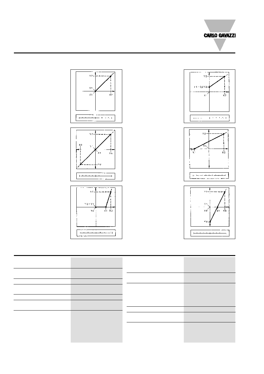
Function Description
Figure A
The sign of measured quant-
ity and output quantity re-
mains the same. The output
quantity is proportional to the
measured quantity.
Input and output scaling capability
Working of the analogue outputs (y) versus input variables (x)
Figure B
The sign of measured quant-
ity and output quantity chan-
ges simultaneously. The out-
put quantity is proportional to
the measured quantity.
Figure C
The sign of measured quant-
ity and output quantity re-
mains the same. On the ran-
ge X0...X1, the output quant-
ity is zero. The range X1...X2
is delineated on the entire
output range Y0 = Y1...Y2
and thus presented in strong-
ly expanded form.
Figure F
The sign of the measured
quantity remains the same,
that of the output quantity
changes as the measured
quantity leaves range X0...X1
and passes to range X1...X2
and vice versa.
Figure E
The sign of the measured
quantity changes but that of
the output quantity remains
the same. The output quant-
ity steadily increases from
value X1 to value X2 of the
measured quantity.
Figure D
The sign of measured quant-
ity and output quantity re-
mains the same. With the
measured quantity being
zero, the output quantity
already has the value
Y1 = 0.2 Y2.
Live zero output.
0 50 A
100
A
0 10 mA
20
mA
-100 kW
0
100 kW
-1 kW
0
1 kW
80 V
100 V
120 V
0 5 mA
10
mA
0 50 A
100
A
4 12 mA
20
mA
-100 kW
0
100 kW
0
10 mA
20 mA
0 50 A
100
A
-1 V
0
1 V
Operating temperature
0 to +50∞C (32 to 122∞F)
(R.H. < 90% non-condensing)
Storage temperature
-10 to +60∞C (14 to 140∞F)
(R.H. < 90% non-condensing)
Insulation reference voltage
300 V
rms
to ground
Insulation
4000 V
rms
between all inputs/
outputs to ground
Dielectric strength
4000 V
rms
for 1 minute
Noise rejection
CMRR
100 dB, 48 to 62 Hz
EMC
EN 50081-2, EN 50082-2
Safety standards
Safety requirements:
IEC 601010-1, EN 61010-1
Products requirements:
IEC 60688-1, EN 60688-1
Connector
Screw-type,
max. 2.5 mm
2
wires
Housing
Dimensions
6 DIN modules,
58.5 x 89 x 107 mm
Material
ABS,
self-extinguishing: UL 94 V-0
Degree of protection
Front: IP50
Weight
Approx. 500 g
(packing included)
Approval
CE
General Specifications
Specifications are subject to change without notice
5
SPT-DIN
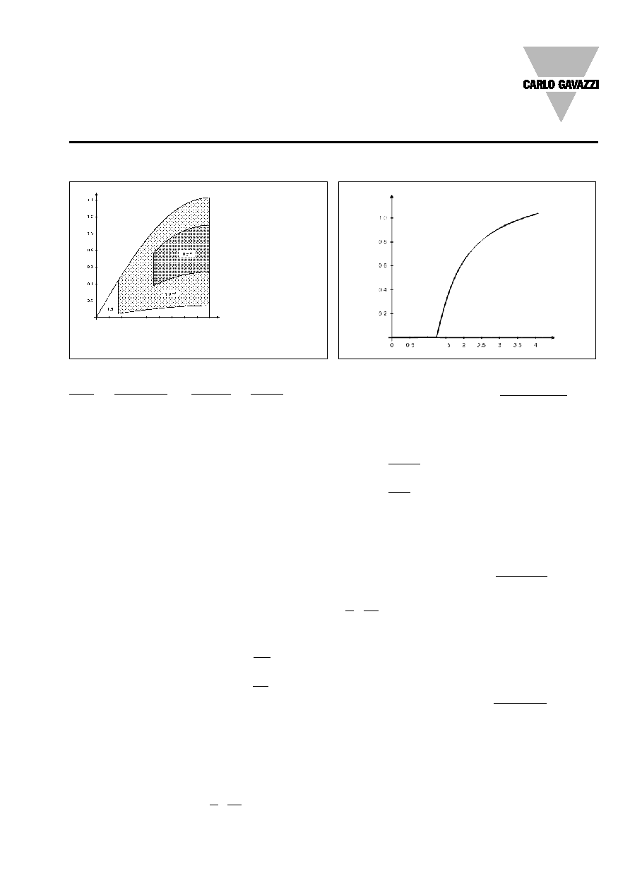
Mode of Operation
Accuracy class of the meter
as a relation of P
I
/P
n
and cos
Trends of the "E" error depending on the S
R
scale ratio
* V = 0.9 to 1.1, Un,
I = 0.6 to 1 In,
f = 48 to 62 Hz
** V = 0.7 to 1.2 Un,
I = 0.2 to 1.2 In,
f = 48 to 100 Hz
80∫ 70∫ 60∫ 50∫
40∫ 30∫ 20∫
10∫
0∫
0.34∫
0.64∫
0.86∫
0.98∫
0.17∫
0.5∫
0.76∫
0.94∫
1∫
E %
S
R
COS
P
I
/P
n
Input
Star Delta
Current
voltage voltage
AV1
Un: 100 V/
3
Un: 100 V
In: 1 A
AV3
Un: 100 V/
3
Un: 100 V
In: 5 A
AV4
Un: 230 V
Un: 398 V
In: 1 A
AV5
Un: 230 V
Un: 398 V
In: 5 A
P
I
(installation power)
One phase system:
P
I
= U
I
∑ I
I
∑ cos
Three phase, 3-wire system:
P
I
=
3 ∑ U
I
∑ I
I
∑ cos
Three phase, 4-wire system:
P
I
= 3 ∑ U
I
∑ I
I
∑ cos
where:
U
I
= the real star voltage of
the electrical system being
measured.
I
I
= the maximum phase cur-
rent of the electrical system
being measured.
Cos
= the average
cos
of
the electrical system being
measured.
P
n
(rated power of transducer)
One phase system:
P
n
= U
n
∑ I
n
∑ VT(ratio) ∑ CT(ratio)
Three phase, 3-wire system:
P
n
=
3 ∑ U
n
∑ I
n
∑ VT(ratio) ∑ CT(ratio)
Three phase, 4-wire system:
P
n
= 3 ∑ U
n
∑ I
n
∑ VT(ratio) ∑ CT(ratio)
where:
U
n
= the rated input voltage of
SPT-DIN depending on the
model, see table above.
I
n
= the rated input current of
SPT-DIN depending on the
model, see table above.
VT (ratio)
= the value of the
voltage transformer ratio.
CT (ratio)
= the value of the
current transformer ratio.
Example 1:
Model AV3.3 (3-wire system).
U
I
=
6 kV (delta voltage)
I
I
= 265 A (single phase cur-
rent)
Cos
= 0.85 (system power
factor)
U
n
= 100 V
I
n
= 5 A
VT (ratio) =
6 kV
= 60
100
CT (ratio) =
300
= 60
5
P
I
=
3 ∑ U
I
∑ I
I
∑ cos
=
3 ∑ 6000 ∑ 265 ∑ 0.85
= 2.33 MW
P
n
=
3 ∑ U
n
∑ I
n
∑ VT(ratio) ∑ CT(ratio)
=
3 ∑ 100 ∑ 5 ∑ 60 ∑ 60
= 3.12 MW
P
I
=
2.33
= 0.75
P
n
3.12
Example 2:
Model AV3.3 (4-wire system).
U
I
=
6 kV /
3
I
I
= 265 A
Cos
= 0.85
U
n
= 100 V /
3
I
n
= 5 A
VT (ratio) =
6 kV /
3
= 60
100 /
3
CT (ratio) =
300 A
= 60
5 A
P
I
= 3 ∑ U
I
∑ I
I
∑ cos
= 3 ∑ 6000 /
3 ∑ 265 ∑ 0.85
= 2.33 MW
P
n
= 3 ∑ U
n
∑ I
n
∑ VT(ratio) ∑ CT(ratio)
= 3 ∑ 100 /
3 ∑ 5 ∑ 60 ∑ 60
= 3.12 MW
P
I
=
2.33
= 0.75
P
n
3.12
In both examples the accura-
cy of the measurement is
0.5% f.s. when considering
the changing of the measur-
ed voltage from 0.9 Un to 1.1
Un and the measured cur-
rent from 0.6 In to 1 In with a
cos
of 0.85. The accuracy
of the output is connected to
the accuracy of the measure-
ment plus the scale ratio of
both input (Hi.E - Lo.E) and
output (Hi.A - Lo.A) as shown
in the graph above (E% ver-
sus S
R
).
Regarding S
R
:
S
R
=
AFS ∑ (Hi.A - Lo.A)
1.25
100 ∑ (Hi.E - Lo.E)
AFS =
automatic electrical full
scale calculated value.
S
R
= scale ratio.
There is not any additional
error on the output signal if
S
R
1.25.
Example 3:
AFS
= 3.30 MW
Lo.E
= 0 MW
Hi.E
= 3.30 MW
Lo.A
= 20%
Hi.A
= 99.9%
S
R
=
3.30 (99.9-20)
= 0.8
100 (3.30-0)
0.8
1.25 no additonal errors
Example 4:
AFS
= 3.30 MW
Lo.E
= 1.00 MW
Hi.E
= 3.30 MW
Lo.A
= 20%
Hi.A
= 99.9%
S
R
=
3.30 (99.9-20)
= 1.32
100 (3-1)
1.32
1.25 means that there
is an additional error of 0.2%
f.s. according to the graph at
the previous page.
6
Specifications are subject to change without notice
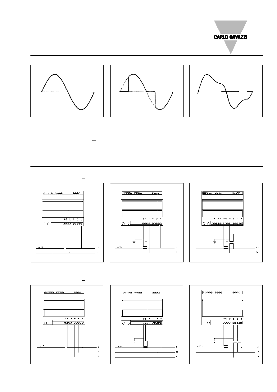
Wiring Diagrams
Single phase input connections
SPT-DIN AV1/AV3/AV4/AV5.1
CT connection
Direct connection
CT and VT connection
Three phase input connections - Balanced loads
SPT-DIN AV1/AV3/AV4/AV5.1
CT connection (3-wire system)
Direct connection (3-wire system)
CT and VT connection (3-wire system)
SPT-DIN
Fig. 2
Fig. 1
Fig. 3
Fig. 4
Fig. 5
Fig. 6
Waveform of the signals that can be measured
Figure G
Sine wave, undistorted
Fundamental content
100%
Harmonic content
0%
A
rms
=
1.1107 | A |
Figure H
Sine wave, indented
Fundamental content
10...100%
Harmonic content
0...90%
Frequency spectrum 3rd to 16th harmonic
Required result: additional error < 1%
Figure I
Sine wave, distorted
Fundamental content
70...90%
Harmonic content
10...30%
Frequency spectrum 3rd to 15th harmonic
Required result: additional error < 0.5%
Mode of Operation (cont.)
Specifications are subject to change without notice
7
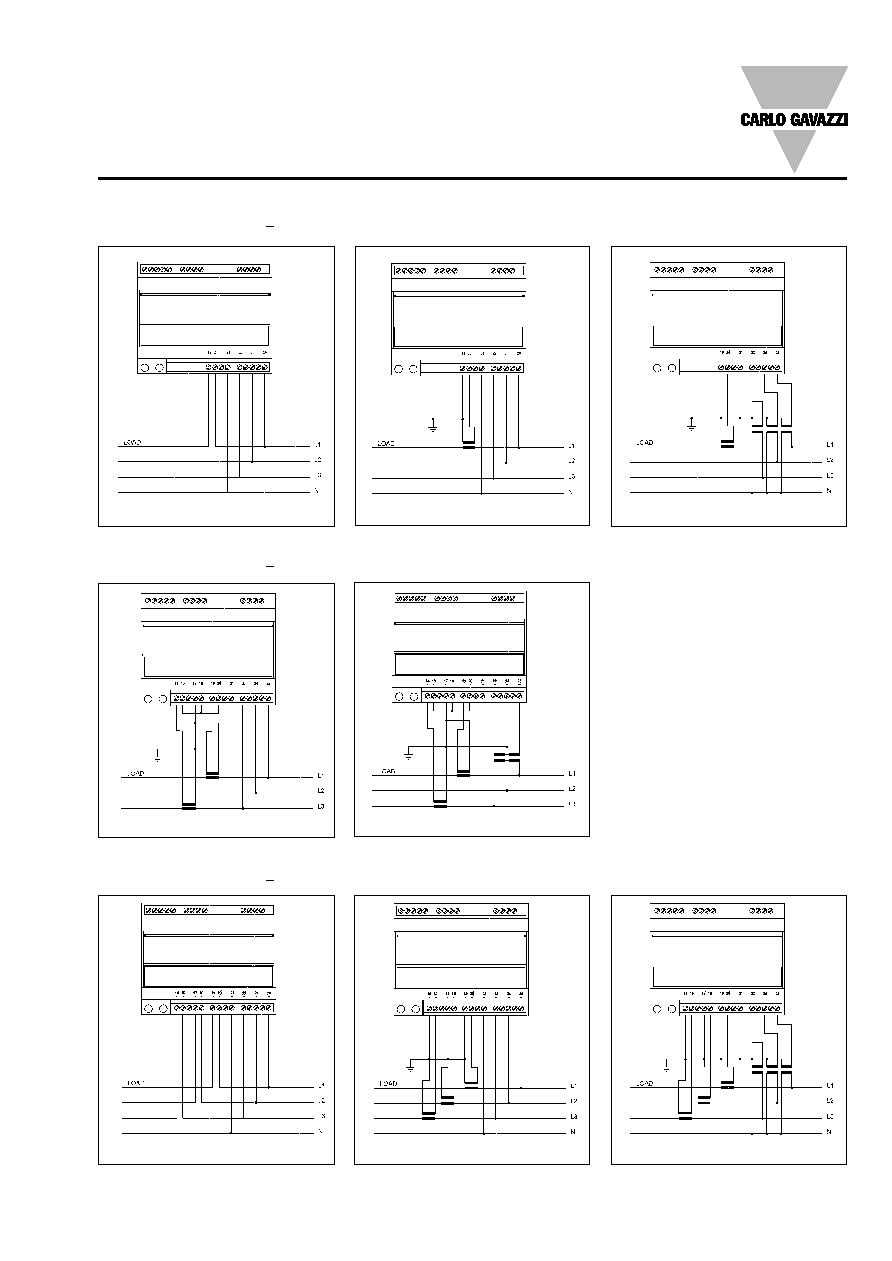
CT connection (4-wire system)
Direct connection (4-wire system)
CT and VT connection (4-wire system)
Wiring Diagrams (cont.)
Three-phase, 3-wire ARON input connections - Unbalanced loads
SPT-DIN AV1/AV3/AV4/AV5.3
CT connection (3-wire system)
CT and VT connection (3-wire system)
Three phase, 4-wire input connections - Unbalanced loads
SPT-DIN AV1/AV3/AV4/AV5.3
Direct connection (4-wire system)
CT connection (4-wire system)
CT and VT connection (4-wire system)
SPT-DIN
Fig. 7
Fig. 8
Fig. 9
Fig. 10
Fig. 11
Fig. 12
Fig. 13
Fig. 14
Three phase input connections - Balanced loads
SPT-DIN AV1/AV3/AV4/AV5.1
8
Specifications are subject to change without notice
SPT-DIN
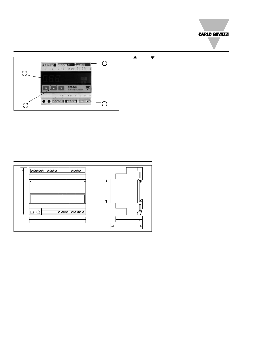
107 mm
89 m
m
49.5 mm
58.5 mm
45 m
m
Dimensions
Front Panel Description
1
" " and " "
- Up and down keys for increasing or decreasing program-
ming values.
- Selecting programming functions and transducer
configuration together with the "S" key.
2. Display
3 -digit (maximum read-out 999).
Alphanumeric indication by means of 7-segment display
for:
- Displaying only the configuration parameters
3. Connection terminal blocks
4. Dip-switch
- For the selection of 2/4 wire connection, line biasing
and/or line termination (only in case of RS 485 option)
1. Key-pad
Set-up and programming procedures are easily controlled
by the 3 pushbuttons.
"S"
- Selection key to select programming function (transducer
configuration) and alarm detection.
2
3
4