
Specifications are subject to change without notice (23.09.2005)
1
Ultrasonic
Diffuse, Analogue Output with Teach-in
Types UA 30 CLD .. .. M1 TI
∑ Cylindrical M30 polyester housing
∑ Sensing distance: 150-1500 mm, 250-2000 mm
or 350-3500 mm
∑ Outputs: Analogue 0-10 V or 4-20 mA and 2 switching
outputs PNP, NO or NC
∑ Teach-in functionality
∑ Power supply: 19 to 30 VDC
∑ 8∞ beam angle
∑ Protection: Short-circuit, reverse polarity, transients
∑ Protection degree IP 67
∑ M12 plug, 5 pin
∑ Repeatability ± 2 mm ± 0.4%
∑ Linearity error ± 0.5% / 3 mm
∑ Hysteresis 1% / 2 mm
Product Description
Ultrasonic sensor
Housing style
Housing size
Housing material
Housing length
Detection principle
Sensing distance
Output type
Output configuration
Connection
Teach-in
Type Selection
Housing
Connection
Rated operating
Analogue output and
Ordering no.
diameter
dist. (S
n
)
2 PNP outputs NO/NC
Teach-in
M30
Plug M12
150-1500 mm
0-10 VDC and 2 x PNP
UA 30 CLD 15 AK M1 TI
M30
Plug M12
250-2000 mm
0-10 VDC and 2 x PNP
UA 30 CLD 20 AK M1 TI
M30
Plug M12
250-2000 mm
4-20 mA and 2 x PNP
UA 30 CLD 20 AG M1 TI
M30
Plug M12
250-2000 mm
2 x PNP
UA 30 CLD 20 PO M1 TI
M30
Plug M12
350-3500 mm
0-10 VDC and 2 x PNP
UA 30 CLD 35 AK M1 TI
Ordering Key UA 30 CLD 35 AK M1 TI
A family of diffuse ultrasonic
sensors with sensing range
from 100-1500 mm, 200-2000
mm and 300-3500 mm with
teach-in adjustment. Adjust-
ments by teach-in makes it
possible to set the analog
angle according to the re-
quests and program the out-
put to NO or NC switching as
well. The outputs are either
0-10 V or 4-20 mA which
make it an ideal choice for
distance measurement, level
measurement, diameter
measurement or loop control
with customised settings. Due
to use of microprocessor con-
trol the digital filtering makes
the sensor immune to most
electromagnetic interferences.
Specifications
Rated operational volt. (U
e
)
19 to 30 VDC
(ripple included)
Ripple
10%
Output current (I
e
)
max. 100 mA (continuous)
for switching outputs
No-load supply current (I
o
)
45 mA
Protection
Short-circuit, transients and
reverse polarity
Rated insulation voltage
> 1 kV
Output
UA30CLD..AKM1TI
Analogue 0-10 VDC,
2 PNP open collector
outputs, NO or NC
UA30CLD20AGM1TI
Analogue 4-20 mA,
2 PNP open collector
outputs, NO or NC
UA30CLD20POM1TI
2 PNP open collector
outputs, NO or NC
Power-on delay
,< 10 ms
Carrier frequency
130 KHz
Voltage drop (U
d
)
4.5 V
Load
4 - 20 mA
max. 500
0 - 10 V
min. 1 k
Off-state current (I
r
)
200
A
Teach-in
Set point adjustment
NO/NC selection
Indication
Set points, 2 LED's
Rated operating distance /
resolution
UA30CLD15 .. M1 TI
150-1500 mm / < 1 mm
UA30CLD20 .. M1 TI
250-2000 mm / < 1 mm
UA30CLD35 .. M1 TI
350-3500 mm / < 1 mm
Operating frequency
1 Hz
Response times
UA30CLD15/20 .. M1 TI
60 ms (target speed 1 m/s)
300 ms (step response)
UA30CLD35 AG M1 TI
120 ms (target speed 1 m/s)
500 ms (step response)

2
Specifications are subject to change without notice (23.09.2005)
Dimensions
UA 30 CLD .. .. M1 TI
Specifications (cont.)
Hysteresis (H)
(differential travel)
1% / 2 mm
Temperature compensation
Yes
Beam angle
8∞
Ambient temperature
Operating
-15∞ to +70∞C (5∞ to +158∞F)
Storage
-25∞ to +85∞C (-13∞ to +185∞F)
Degree of protection
IP 67 (Nema 1, 3, 4, 6, 13)
150 mm
1500 mm
300 mm
300 mm
250 mm
2000 mm
350 mm
3500 mm
UA 30 ... 15
UA 30 ... 20
UA 30 ... 35
Detection Range
Cable Wiring
1
4
5
2
3
SP1
BN
BU
SP2
Guaranteed detection of a
target 100 x 100 mm
Possible detection of a
large target
20
S
n max
mA
S
n min
4
10
S
n max
V
S
n min
0
Analogue Output Curves
Housing material
Polyester PBTP
Connection
Plug M12, 5-pin
Cable CONM15 series
Weight
148 g
Tightening torque
7.5 Nm
CE-marking
Yes
Switching Operation
D ist anc e
SP 1
SP 2
SP 1
SP 2
P1
P2
P1 P2
P1
P2
Distance
P1
P2
Distance
NO Characteristics
NC Characteristics
Normal Switching Operation
Specifications are subject to change without notice (23.09.2005)
3
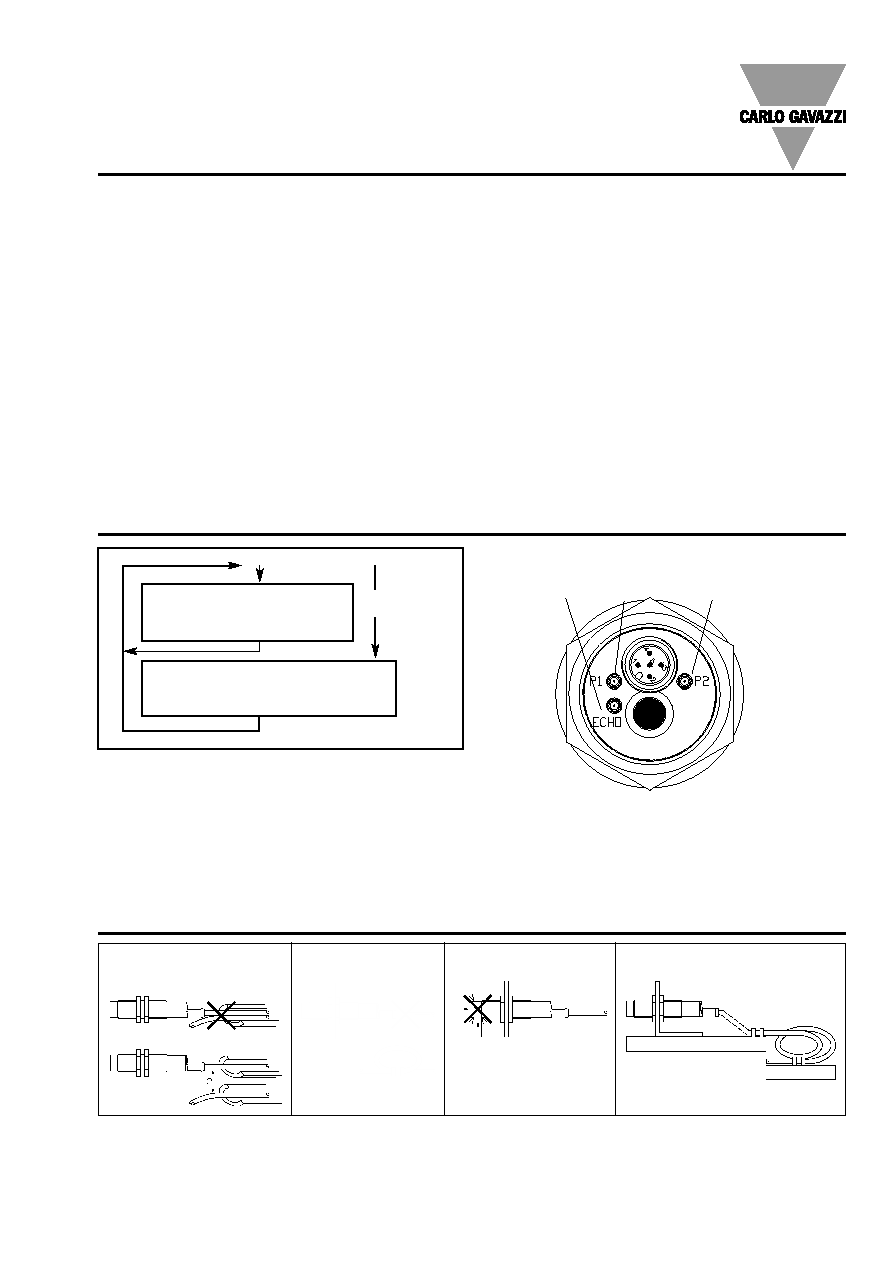
Installation Hints
Relief of cable strain
Protection of the sensing face
Switch mounted on mobile carrier
To avoid interference from inductive voltage/
current peaks, separate the prox. switch
power cables from any other power cables,
e.g. motor, contactor or solenoid cables
Incorrect
Correct
The cable should not be pulled
A proximity switch should not serve as
mechanical stop
Any repetitive flexing of the
cable should be avoided
Analogue output adjustment
P1 and P2 define the analogue output slope.
P1 determines the 4 mA/0V position and P2 the 20 mA/10V
position.
Positive slope:
P1 < P2
Negative slope:
P2 < P1
Teach-In of P1 position (4 mA/0V and SP1 output)
Hold Teach-In for 17 seconds until P1 and Echo LED's start
flashing 2 times per second.
The sensor is now in teach mode for P1:
P1 LED will now flash once per second and the Echo LED
returns to normal function (alignment LED).
The Teach-In function is now open for 1 minute to do the
programming of P1.
Place the target at the new position P1.
Activate Teach-in: P1 is now programmed.
Sensor returns to normal function with new value for P1.
Teach-In of P2 position (20 mA/10V and SP2 output)
Hold Teach-In for 20 seconds until the P2 and Echo LEDs
start flashing 2 times per second. After 8 seconds, the P1
and Echo LEDs will start flashing, but this must be ignored
and after an additional 5 seconds the P2 is reached.
The sensor is now in teach mode for P2:
P1 LED is flashing once per second. The Echo LED returns
to normal function (alignment LED).
Teach-mode is now open for 1 minute to do the program-
ming of P1.
Move the target to the new position P2.
Activate Teach-in: P2 is now programmed.
Sensor returns to normal function with new value for P2.
Switching output characteristics can be selected during
teaching of the set point P1 or P2. If activating the Teach-In
as the LED is ON ≠ the switching output will have NO
characteristics, if doing this as the LED is OFF, the switching
output will have NC characteristics.
Teach-in procedure
Teach in of P1 position
Teach in of P2 position
Teach-In for
17 sec
14 sec
Normal function:
The Echo LED is ON when the echo is received (this is the
alignment LED confirming that the target is properly aligned).
The LED P1 is ON, when the target is between the sensor
face and P1. The LED P2 is ON when Target is farther than
P2.
Teach-In for
20 sec
Output Adjustment
Switching output can be either NO or NC
Switching output can be either NO or NC
Echo
P1
P2
Green
Yellow
Yellow