Specifications are subject to change without notice (19.06.2006)
1
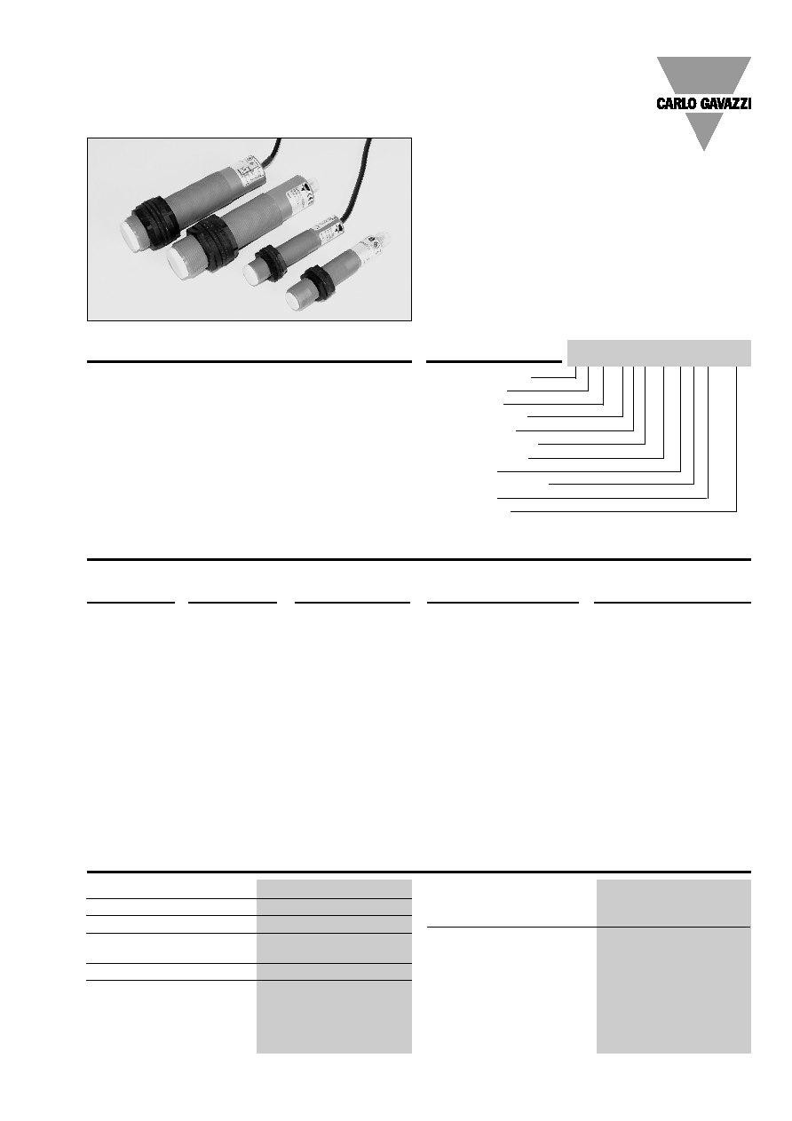
Ultrasonic
Diffuse, Analogue Output
Type M18 and M30
Product Description
Ultrasonic sensor
Housing style
Housing size
Housing material
Housing length
Detection principle
Sensing distance
Output type
Output configuration
Connection
Remote teach
Type Selection
Housing Connection
Rated
operating
Outputs
Ordering
no.
dimensions
dist. (S
n
)
M18 x 93 mm
Plug M12, 5 pin
60-500 mm
0-10 V
UA18CLD05AKM1TR
M18 x 93 mm
Cable
60-500 mm
0-10 V
UA18CLD05AKTR
M18 x 93 mm
Plug M12, 5 pin
60-500 mm
4-20 mA
UA18CLD05AGM1TR
M18 x 93 mm
Cable
60-500 mm
4-20 mA
UA18CLD05AGTR
M18 x 93 mm
Plug M12, 5 pin
100-800 mm
0-10 V
UA18CLD08AKM1TR
M18 x 93 mm
Cable
100-800 mm
0-10 V
UA18CLD08AKTR
M18 x 93 mm
Plug M12, 5 pin
100-800 mm
4-20 mA
UA18CLD08AGM1TR
M18 x 93 mm
Cable
100-800 mm
4-20 mA
UA18CLD08AGTR
M18 x 93 mm
Plug M12, 5 pin
200-2000 mm
0-10 V
UA18CLD20AKM1TR
M18 x 93 mm
Cable
200-2000 mm
0-10 V
UA18CLD20AKTR
M18 x 93 mm
Plug M12, 5 pin
200-2000 mm
4-20 mA
UA18CLD20AGM1TR
M18 x 93 mm
Cable
200-2000 mm
4-20 mA
UA18CLD20AGTR
M30 x 125 mm
Plug M12, 5 pin
300-3500 mm
0-10 V
UA30CLD35AKM1TR
M30 x 123.5 mm
Cable
300-3500 mm
0-10 V
UA30CLD35AKTR
M30 x 125 mm
Plug M12, 5 pin
300-3500 mm
4-20 mA
UA30CLD35AGM1TR
M30 x 123.5 mm
Cable
300-3500 mm
4-20 mA
UA30CLD35AGTR
Ordering Key UA18CLD20AKM1TR
A family of multi function dif-
fuse ultrasonic sensors with
a sensing range of 60 to
3500 mm. The analog output
is easily set up in 2 setpoints
(pos./neg. slope) and adjust-
ed by teach-in - makes it
ideal for level control tasks in
a wide variety of vessels. A
sturdy one-piece PBT
housing provides the perfect
packaging for the sofisticat-
ed microprocessor con-
trolled and digitally filtered
sensor electronics. Excellent
EMC performance and pre-
cision are typical features of
this sensor based on true
distance measurement.
Technical Data
Rated operational volt. (Ue)
15 to 30 VDC (ripple included)
Ripple
10%
No-load supply current (Io)
40 mA
Protection
Short-circuit, transients and
reverse polarity
Rated insulation voltage
> 1 kV
Power-on delay
UA18..D05/D08
60 ms
UA18..D20
90 ms
UA18..D35
220 ms
Output
UA..CLD..AK..
0-10 VDC
UA..CLD..AG..
4-20 mA
Output slope
Positive or negative
Setup via teach-in
� M18 and M30 PBT housing
� Sensing distance: 60 - 3500 mm
� Remote Teach by wire
� Outputs: Analog 0-10 V or 4-20 mA
� Setup of positive or negative slope
� Power supply: 15 to 30 VDC
� 8� beam angle
� Protection: Short-circuit, reverse polarity, transients
� Protection degree IP 67
� M12 plug, 5 pin

2
Specifications are subject to change without notice (19.06.2006)
+
-
1 BN
3 BU
4 WH
Teach-in
5 PK
(GY)
5
3
2
1
4
M18 and M30
Analogue Output Adjustment
1
2
3
4
5
Echo P1 P2
Green Yellow Yellow
Teach in of P1 position
Teach in of P2 position
Teach-In for
8 sec
14 sec
Normal function:
The Echo LED is ON when the echo is received (this is the
alignment LED confirming that the target is properly aligned).
The LED P1 is ON, when the target is between the sensor
face and P1. The LED P2 is ON when Target is farther than
P2.
Wiring Diagram
Teach-In for
14 sec
Linearity error
< 0.5%
Repeat accuracy (R)
UA....D05/08
0.2%; 1 mm
UA....D20/35
0.2%: 2 mm
Rated operating distance/
Resolution*
UA18CLD05
60-500 mm:
0.25 mm
UA18CLD08
100-800 mm:
0.25 mm
UA18CLD20 200-2000
mm:
1.0
mm
UA30CLD35
300-3500 mm:
1.0 mm
Load
4-20 mA
max. 500
0-10 V
min. 1 k
Carrier frequency
UA....D05
330 KHz
UA....D08
300 KHz
UA....D20
180 KHz
UA....D35
130 KHz
Response time
UA18CLD05/08
100 ms
UA18CLD20 200
ms
UA30CLD35
400 ms
Technical Data (cont.)
Indication
Set points, 2 LEDs yellow
Echo, 1 LED green
Rated operating distance
60 - 3500 mm
Temperature compensation
Yes
Beam angle
8�
Ambient temperature
Operating and Storage
-15� to +70�C (5� to +158�F)
Degree of protection
IP 67 (Nema 1, 3, 4, 6, 13)
Housing material
Polyester, PBTP
Connection
Cable
2 m, 5 x 0.25 mm
2
Plug
M12, 5-pin
Cables for plug (M1)
CONM15 series
WeightWeight
UA 18 ...A.
96 g
UA 18 ...A.M1 57 g
UA 30 ...A.
199 g
UA 30 ...A.M1 140 g
Tightening torque
M18
2.6 Nm
M30
7.5 Nm
CE-marking
Yes

Specifications are subject to change without notice (19.06.2006)
3
M18 and M30
Detection Range
0
60
500
mm
mm
-150
+150
93
� 0.5
65
� 0.1
M18 x 1
Dimensions
93
� 0.5
65
� 0.1
M18 x 1
123.5
� 0.5
90
� 0.5
5
M30 x 1.5
125
� 0.5
11.2
90
� 0.5
5
M30 x 1.5
M18 cable
M18 plug
M30 cable
M30 plug
UA18CLD05
0
100
800
mm
mm
-150
+150
UA18CLD08
0
200
2000
mm
mm
+400
-400
UA18CLD20
0
300
3500
mm
mm
-800
+800
UA30CLD35
Guaranteed detection of a target 100 x 100 mm
Guaranteed detection of a target 100 x 100 mm
Guaranteed detection of a target 100 x 100 mm
Guaranteed detection of a target 100 x 100 mm
Possible detection of a large target
Possible detection of a large target
Possible detection of a large target
Possible detection of a large target
4
Specifications are subject to change without notice (19.06.2006)
V
10
0
200
2000 mm
V
10
0
100
800 mm
V
10
0
60
500 mm
V
10
0
300
3500 mm
Analogue output adjustment
P1 and P2 define the analogue output slope.
P1 determines the 4 mA position and P2 the 20 mA position.
Positive slope:
P1 < P2
Negative slope:
P2 < P1
Teach-In of P1 position (4 mA output)
Hold Teach-In for 8 seconds until P1 and Echo LED's start
flashing 2 times per second.
The sensor is now in teach mode for P1:
P1 LED will now flash once per second and the Echo LED
returns to normal function (alignment LED).
The Teach-In function is now open for 1 minute to do the
programming of P1.
Place the target at the new position P1.
Activate Teach-in: P1 is now programmed.
Sensor returns to normal function with new value for P1.
Teach-In of P2 position (20 mA output)
Hold Teach-In for 14 seconds until the P2 and Echo LEDs
start flashing 2 times per second. After 8 seconds, the P1
and Echo LEDs will start flashing, but this must be ignored
and after an additional 5 seconds the P2 is reached.
The sensor is now in teach mode for P2:
P2 LED is flashing once per second. The Echo LED returns
to normal function (alignment LED).
Teach-mode is now open for 1 minute to do the program-
ming of P2.
Move the target to the new position P2.
Activate Teach-in: P2 is now programmed.
Sensor returns to normal function with new value for P2.
Teach-in procedure
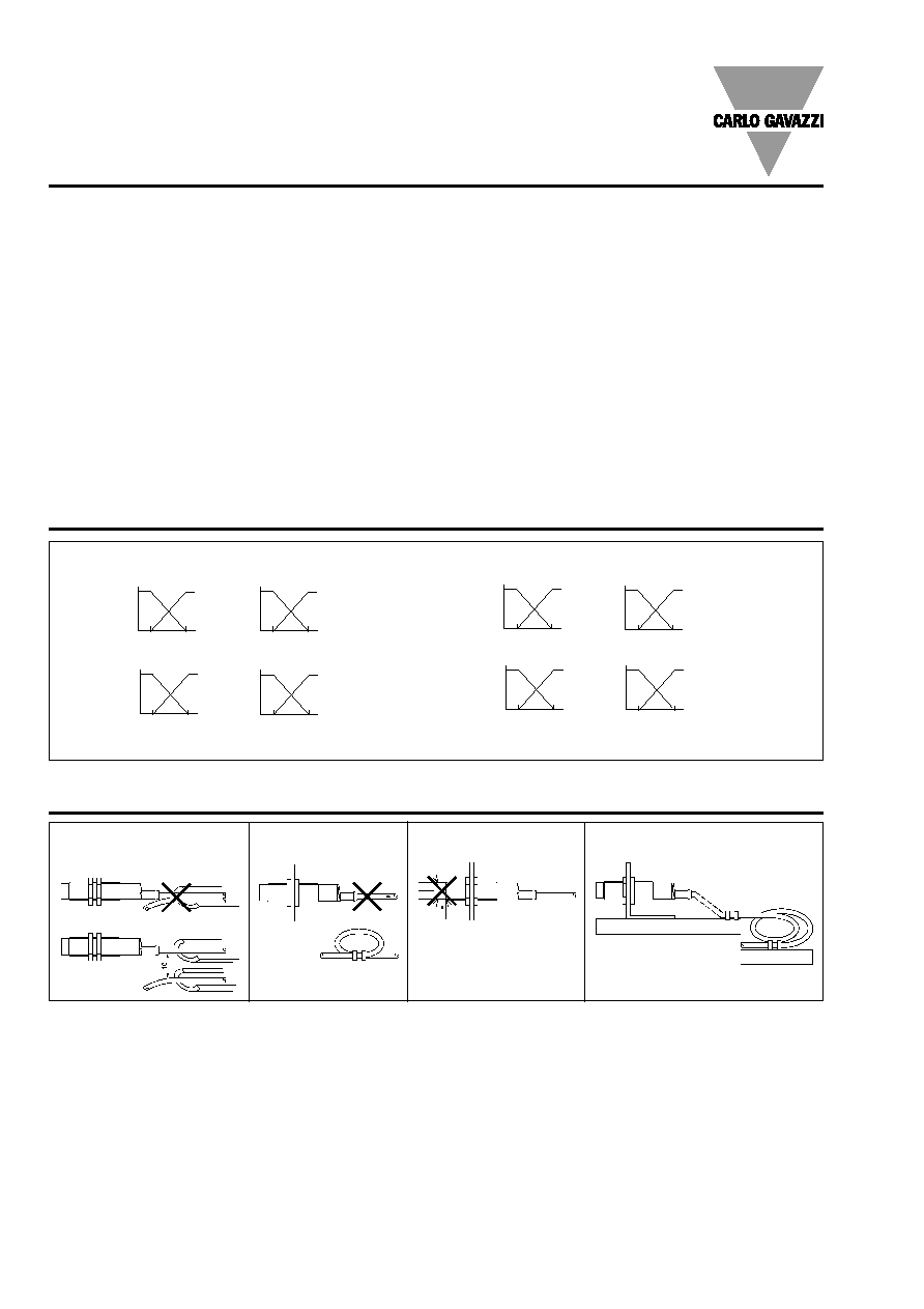
Installation Hints
Relief of cable strain
Protection of the sensing face
Switch mounted on mobile carrier
To avoid interference from inductive voltage/
current peaks, separate the prox. switch
power cables from any other power cables,
e.g. motor, contactor or solenoid cables
Incorrect
Correct
The cable should not be pulled
A proximity switch should not serve as
mechanical stop
Any repetitive flexing of the
cable should be avoided
M18 and M30
Output Functions
Voltage
Output
mA
20
4
200
2000 mm
mA
20
4
100
800 mm
mA
20
4
300
3500 mm
mA
20
4
60
500 mm
Current
Output