
Specifications are subject to change without notice (22.07.2005)
1
Ultrasonic
Evaluation Unit for Sensor Head
Type UC EU 80 -1
∑ 100 x 75 x 110 mm housing, DIN-rail mounting
∑ Outputs: PLC, Display, RS232, sensor supply
∑ Input: Sensor head UC 80 CND 80 FS M1
∑ Full programmable
∑ Hold function, 2 set points, over- and under range,
analogue outputs 0-10 VDC and 4-20 mA
∑ Power supply: 24 VDC unregulated (19 to 30 VDC)
∑ Protection: Short-circuit, reverse polarity, transients
∑ Protection degree IP 40
∑ Screw terminals
∑ Distance to sensor head: up to 50 m
Product Description
Ultrasonic sensor
Housing style
Evaluation unit
Sensing distance
Variant
Type Selection
Housing Connection
Rated
operating
Ordering
no.
dimensions
dist. (S
n
)
100 x 75 x 110 mm
Screw terminals
800-8000 mm
UC EU 80 -1
Ordering Key
UC EU 80 -1
Evaluation unit for sensor
head UC80CND80FSM1.
From the evaluation unit it is
possible to program all sensor
settings e.g. sensitivity, NO or
NC switching and angle of
analog output. As the sensor
and evaluation unit is sepa-
rated it makes the two-part
set-up an ideal solution for
level measurement in high
tanks. When the evaluation
unit is mounted in a panel all
settings can be fixed here and
not on the top of the tank.
Specifications
Rated operational volt. (U
e
)
19 to 30 VDC
(ripple included)
Ripple
10%
Protection
Short-circuit, transients and
reverse polarity
Rated insulation voltage
> 1 kV
Inputs
Sensor head
Pins 3, 4, 5, 6, 8
Hold
Pin 10 (active LO)
Outputs
Set point 1
Pin 14
Set point 2
Pin 15
Over range
Pin 12
Under range
Pin 13
Analogue output, 0-10 VDC
Pin 16, R
min
1450
Analogue output, 4-20 mA
Pin 18, R
max
250
Display
BCD, pins 23-26
HEX, pins 27-30
NPN, open collector,
30 VDC, 20 mA, short-
circuit protected
Carrier frequency
65 kHz
Programmable functions
Basic set-up, saving of basic
set-up, analogue output
range and offset, set points,
over- and under range, repe-
tition frequency, false echos,
read-out of parameters,
mode register.
Rated operating distance
800-8000 mm
Ambient temperature
Operating
0∞ to +50∞C (32∞ to +122∞F)
Storage
-25∞ to +85∞C (-13∞ to +185∞F)
Degree of protection
IP 40
Housing material
ABS (Teluran 877T)
Housing dimensions
100 x 75 x 110 mm
Connection
Screw terminals
Weight
370 g
CE-marking
Yes
PNP, open collector
100 mA, Short
circuit protected
2
Specifications are subject to change without notice (22.07.2005)
Dimensions
UC EU 80 -1
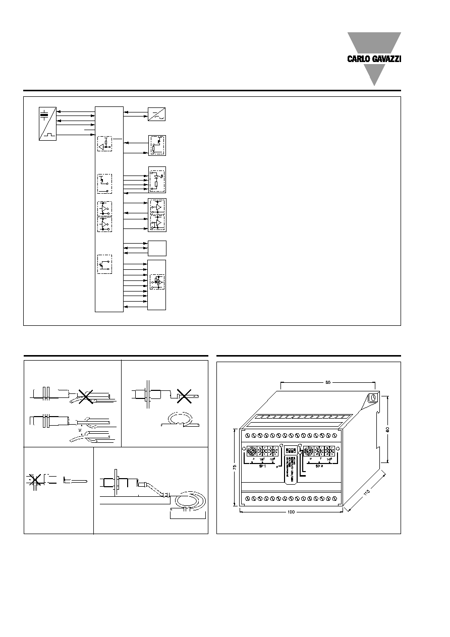
Wiring
Installation Hints
Relief of cable strain
Protection of the sensing face
Switch mounted on mobile carrier
To avoid interference from inductive voltage/
current peaks, separate the prox. switch
power cables from any other power cables,
e.g. motor, contactor or solenoid cables
Incorrect
Correct
The cable should not be pulled
A proximity switch should not
serve as mechanical stop
Any repetitive flexing of the
cable should be avoided
External power supply
1
24 V
Power supply
2
GND
Ground, power supply
Sensor head UC80CND80FSM1
3 24
V Sensor
supply
4
GND
Ground, sensor supply
5 STA Transmit
pulse
6 STO Received
pulse
7 SEN Receiver
sensitivity
(not connected)
8
TEM
Temperature signal
Remote control
9 GND Ground
10 HLD Transmit
disable,
synchronisation
Switching outputs
11 GND Ground
12 ORA Over
Range,
no received pulse
13 URA Under
Range,
"blind zone"
14
SP1
Setpoint 1
15
SP2
Setpoint 2
Analogue outputs
16
U
Voltage output 0... 10V
17
GND
Ground for voltage output
18
I
Current output 4... 20mA
19
GND
Ground for current output
Interface, serial output (UDSProg A4N)
20
TxD
Data output, serial
21
GND
Ground, Data output, serial
22 RxD
Data
input,
serial
24V-
GND
STA
STO
TEM
24V-
GND
-
+
+
-
HLD
GND
SP1
SP2
ORA
URA
GND
4,7k
U
GND
I
GND
SEN
RS232
TxD
GND
RXD
RxD
GND
TXD
10
10
10
10
2
2
2
GND
2
3
2
1
0
3
2
1
0
Display
Interface
1
2
3
4
5
3
4
5
6
7
8
1
2
10
9
14
15
12
13
11
16
17
18
17
20
21
22
23
24
25
26
27
28
29
30
21
Display outputs
23 10
3
Digit 3
24 10
2
Digit 2
25 10
1
Digit 1
26 10
0
Digit 0
27 2
3
Digit 3
28 2
2
Digit 2
29 2
1
Digit 1
30 2
0
Digit 0