
Specifications are subject to change without notice WM12-DINDS 110806
1
∑ Accuracy ±0.5 F.S. (current/voltage)
∑ Multifunction indicator
∑ Display of instantaneous variables: 3x3 digit
∑ Variable system and phase measurements: W, W
dmd
,
var, VA, VA
dmd
, PF, V, A, An, Hz
∑ A
max
, W
dmd max
indication
∑ TRMS meas. of distorted sine waves (voltages/currents)
∑ Power supply: 24V, 48V, 115V, 230V, 50-60Hz; 18 to 60VDC
∑ Protection degree (front): IP 40
∑ Front dimensions: 6 DIN modules
∑ Optional RS422/485 serial output
∑ Alarms (visual only) V LN, An
Product Description
3-phase multifunction power
indicator with built-in pro-
gramming key-pad. Particu-
larly recommended for dis-
playing the main electrical
variables.
Housing for DIN-rail mount-
ing, (front) protection degree
IP40 and optional RS485
serial output.
Energy Management
Multifunction indicator
Type WM12-DIN
Model
Range code
System
Power supply
Option
How to order
WM12-DIN AV5 3 D X
Type Selection
Power supply
A:
24VAC
-15+10%, 50-60Hz
B:
48VAC
-15+10%, 50-60Hz
C:
115VAC
-15+10%, 50-60Hz
D:
230VAC
-15+10%, 50-60Hz
3:
18 to 60VDC
Range codes
AV5:
380/660V
L-L
/5(6)AAC
VL-N: 185 V to 460 V
VL-L: 320 V to 800 V
AV6:
120/208V
L-L
/5(6)AAC
VL-N: 45 V to 145 V
VL-L: 78 V to 250 V
Phase current: 0.03A to 6A
Neutral current: 0.09 to 6A
Options
X:
None
S:
RS485 output
System
3 :
1-2-3-phase,
unbalanced load,
with or without
neutral
Rated inputs
Current
3 (shunt)
Voltage
4
Accuracy (display, RS485)
with CT=1 and VT=1 AV5:
(@25∞C ±5∞C, R.H.
60%)
1150W-VA-var, FS:230VLN,
400VLL; AV6: 285W-VA-var,
FS:57VLN, 100VLL
Current
0.25 to 6A: ±(0.5% FS +1DGT)
0.03A to 0.25A: ±7DGT
Neutral current
0.25 to 6A: ±(1.5% FS +1DGT)
0.09A to 0.25A: ±7DGT
Phase-phase voltage
±(1.5% FS +1 DGT)
Phase-neutral voltage
±(0.5% FS + 1 DGT)
Active and Apparent power,
0.25 to 6A: ±(1% FS +1DGT);
Power factor
0.03A to 0.25A: ±(1% FS
+5DGT)
Reactive power
0.25 to 6A: ±(2% FS +1DGT);
0.03A to 0.25A: ±(2% FS
+5DGT)
Frequency
±0.1%Hz (48 to 62Hz)
Additional errors
Humidity
0.3% FS, 60% to 90% RH
Temperature drift
200ppm/∞C
Sampling rate
1400 samples/s @ 50Hz
1700 samples/s @ 60Hz
Display refresh time
700ms
Display
Type
LED, 9mm
Read-out for the instant. var.
3x3 DGT
Measurements
Current, voltage, power,
power factor, frequency
TRMS measurement of
distorted waves.
Coupling type
Direct
Crest factor
< 3, max 10A peak
Input impedance
380/660V
L-L
(AV5)
1 M
±5%
120/208V
L-L
(AV6)
453 K
±5%
Current
0.02
Frequency
48 to 62 Hz
Overload protection
Continuous voltage/current
1.2 F.S.
For 500ms: voltage/current
2 Un/36A
Input specifications
2
Specifications are subject to change without notice WM12-DINDS 110806
WM12-DIN
Data (bidirectional)
Dynamic (reading only)
System and phase variables
Static (writing only)
All configuration parameters
Data format
1 bit di start , 8 data bit,
no parity, 1 stop bit
Baud-rate
9600 bit/s
RS422/RS485 (on request)
Type
Multidrop
bidirectional (static and
dynamic variables)
Connections
2 or 4 wires, max. distance
1200m, termination directly
on the instrument
Addresses
1 to 255, key-pad selectable
Protocol
MODBUS/JBUS
RS485 Serial Output Specifications
Displaying
Up to 3 variables per page
3-phase system with neutral
Page 1: V L1, V L2, V L3
Page 2: V L12, V L23, V L31
Page 3: A L1, A L2, A L3
Page 4: An
Page 5: WL1, WL2, WL3
Page 6: PF L1, PF L2,
PF L3
Page 7: var L1, var L2, var L3
Page 8: VA L1, VA L2, VA L3
Page 9: VA
, W , var
Page 10: VA dmd, W dmd,
Hz
Page 11: W dmd MAX
Page 12: VL-L
, PF
Page 13: A MAX
Alarms
Programmable, for the VL
and
An (neutral current).
Note: the alarm is only visual,
by means of LED on the front
of the instrument.
Reset
Independent
alarm (VL
, An)
max: A, Wdmd
Password
Numeric code of max. 3
digits; 2 protection levels
of the programming data
1st level
Password "0", no
protection
2nd level
Password from 1 to 999,
all data are protected
System selection
3-phase with neutral
3-phase without neutral
3-phase ARON
2-phase
Single phase
Transformer ratio
CT
1 to 999
VT
1.0 to 99.9
Filter
Operating range
0 to 99.9% of the input
electrical scale
Filtering coefficient
1 to 16
Filter action
Measurements, alarms,
serial output
(fundamental variables: V, A,
W and their derived ones).
Software functions
Auxiliary power supply
230VAC
-15 +10%, 50-60Hz
115VAC
-15 +10%, 50-60Hz
48VAC
-15 +10%, 50-60Hz
24VAC
-15 +10%, 50-60Hz
18 to 60VDC
Power consumption
AC: 4.5 VA
DC: 4W
Power Supply Specifications
500VAC/DC between
measuring inputs and RS485.
4000VAC, 500VDC between
power supply and RS485.
Dielectric strength
4000 VAC (for 1 minute)
EMC
Emissions
EN50084-1 (class A)
residential environment,
commerce and light industry
Operating
0 to +50∞C (32 to 122∞F)
temperature
(RH < 90% non condensing at
40∞C)
Storage
-30 to +60∞C (-22 to 140∞F)
temperature
(RH < 90% non condensing at
40∞C)
Installation category
Cat. III (IEC 60664, EN60664)
Insulation (for 1 minute)
4000VAC, 500VDC
between measuring
inputs and power supply.
General Specifications

Specifications are subject to change without notice WM12-DINDS 110806
3
WM12-DIN
General Specifications (cont.)
Waveform of the signals that can be measured
Figure A
Sine wave, undistorted
Fundamental content
100%
Harmonic content
0%
A
rms
=
1.1107 | A |
Figure B
Sine wave, indented
Fundamental content
10...100%
Harmonic content
0...90%
Frequency spectrum: 3rd to 16th harmonic
Additional error: <1% FS
Figure C
Sine wave, distorted
Fundamental content
70...90%
Harmonic content
10...30%
Frequency spectrum: 3rd to 16th harmonic
Additional error: <0.5% FS
Immunity
EN 61000-6-2 (class A)
industrial environment.
Pulse voltage (1.2/50µs)
EN61000-4-5
Safety standards
IEC 60664, EN60664
Approvals
CE, UL
Connections 5(6) A
Screw-type
Max cable cross sect. area
2.5 mm
2
Housing
Dimensions (WxHxD)
107.8 x 80 x 64.5 mm
Material
ABS
self-extinguishing: UL 94 V-0
Mounting
DIN-rail
Protection degree
Front: IP40
Connections: IP20
Weight
Approx. 400 g (pack. incl.)
Display variables in 3-phase systems (in a 3-phase system with neutral)
No
1
st
variable
2
nd
variable
3
rd
variable
Note
1
V L1
V L2
V L3
2
V L12
V L23
V L31
Decimal point blinking on the right
of the display
3
A L1
A L2
A L3
4
An
AL.n
AL.n if neutral current alarm is
active
5
W L1
W L2
W L3
Decimal point blinking on the right
of the display if generated power
6
PF L1
PF L2
PF L3
7
VAR L1
VAR L2
VAR L3
Decimal point blinking on the right
of the display if generated power
8
VA L1
VA L2
VA L3
9
VA system
W system
VAR system
10
VA dmd
W dmd
Hz
dmd = demand (integration time
(system)
(system)
(system)
selectable from 1 to 30 minutes)
11
W dmd MAX
Maximum sys power demand
12
V LL system
AL.U
PF system
AL.U= is activated only if one of
VLN is not within the set limits
13
A MAX
max. current among the three phases
Display pages
4
Specifications are subject to change without notice WM12-DINDS 110806
WM12-DIN
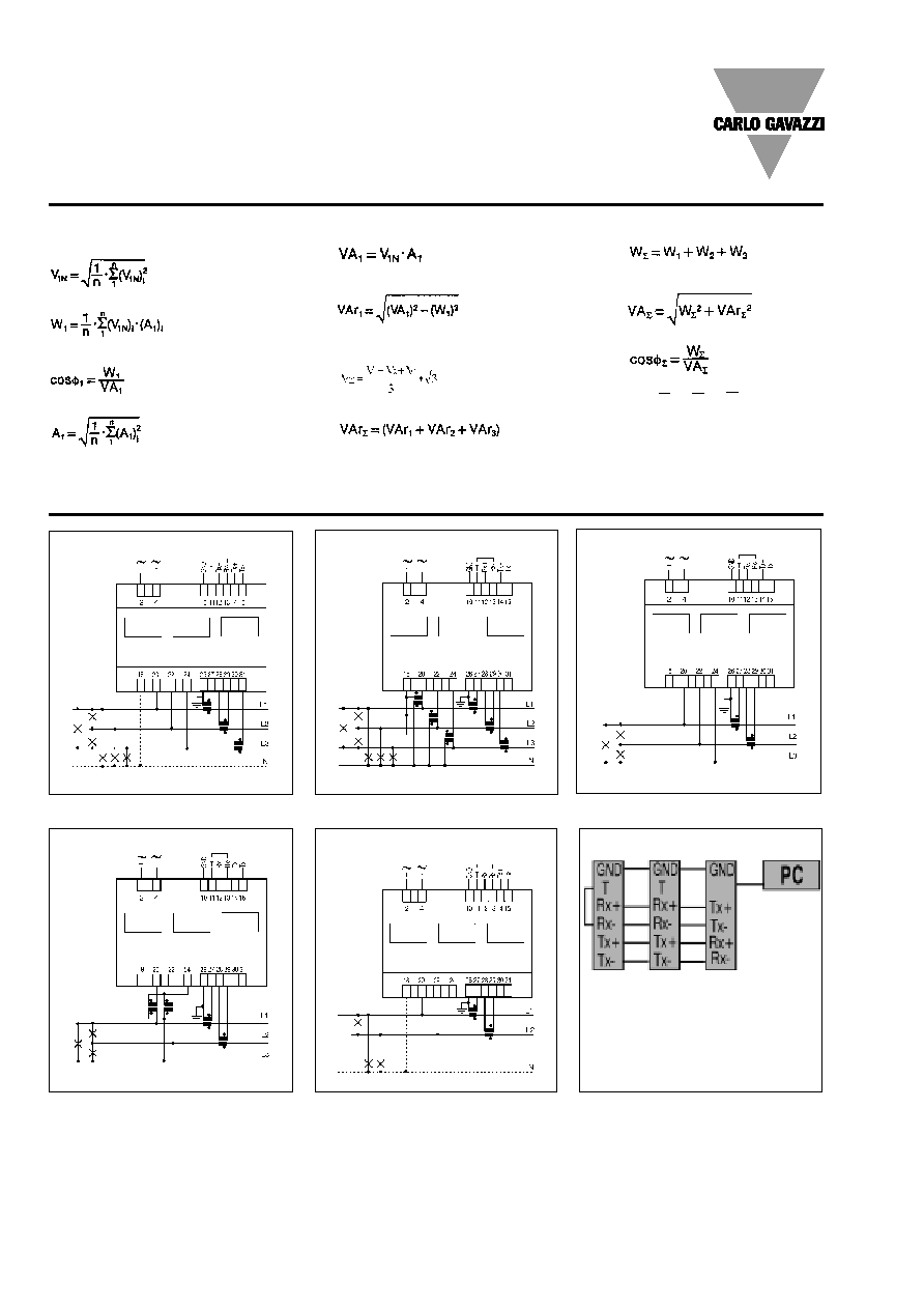
Wiring diagrams
Used calculation formulas
ARON connection
3CT and 3VT connection
CT connection
Fig. 3
ARON and VT connection
2-phase connection
[1] [2] [3]
1-Last instrument
2-1...n Instrument
3-SIU-PC
4-wire connection
Fig. 4
Fig. 2
Fig. 1
Fig. 5
RS485 serial connection
Fig. 6
Instantaneous apparent power
Instantaneous reactive power
System variables
Equivalent 3-phase voltage
3-phase reactive power
Phase variables
Instantaneous effective voltage
Instantaneous active power
Instantaneous power factor
Instantaneous effective current
3-phase active power
3-phase apparent power
3-phase power factor
Neutral current
NOTE: the current inputs can be connected to the lines ONLY by means of current transform-
ers. The direct connection is not allowed.
ATTENTION: Only one ammeter input can be connected to earth, as shown in the electrical dia-
grams.
An = A
L1
+ A
L2
+ A
L3
Specifications are subject to change without notice WM12-DINDS 110806
5
WM12-DIN
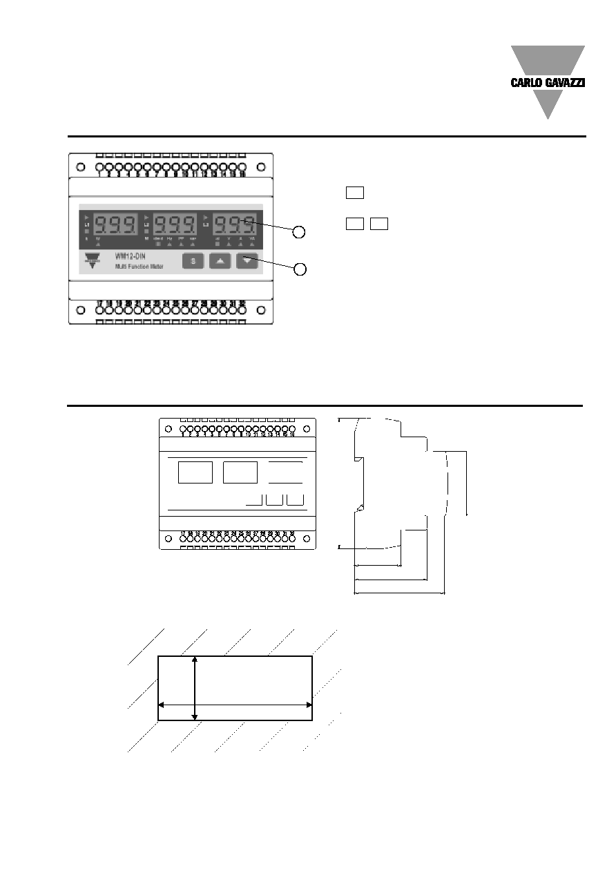
1. Key-pad
To program the configuration parameters and the display of
the variables.
Key to enter programming and confirm selections;
Keys to:
- programme values;
- select functions;
- display measuring pages.
2. Display
LED-type with alphanumeric indications to:
- display configuration parameters;
- display all the measured variables.
L
L
L
L
S
Front Panel Description
Dimensions and Panel Cut-out
1
2
107,8mm
64,5mm
50,1mm
32,2mm
4
4
m
m
9
0
m
m
108,5mm
4
5
m
m