Specifications are subject to change without notice WM14-96PDS190706
1
∑
Class 1 (active energy)
∑
Class 2 (reactive energy)
∑
Accuracy ±0.5 F.S. (current/voltage)
∑
Power analyzer
∑
Display of instantaneous variables: 3x3 digit
∑
Display of energies: 8+1 digit
∑
System variables and phase measurements: W, W
dmd
,
var, VA, VA
dmd
, PF, V, A, An, A
dmd
, Hz
∑
A
max
, A
dmd max
, W
dmd max
indication
∑
Energy measurements: kWh and kvarh
∑
Hour counter (5+2 DGT)
∑
TRMS meas. of distorted sine waves (voltages/currents)
∑
Galvanically insulated measuring inputs
∑
Profibus DP-V0 serial port
∑
Alarms (visual only) V
LN
, An
∑
Power supply: 90 to 260VAC/DC
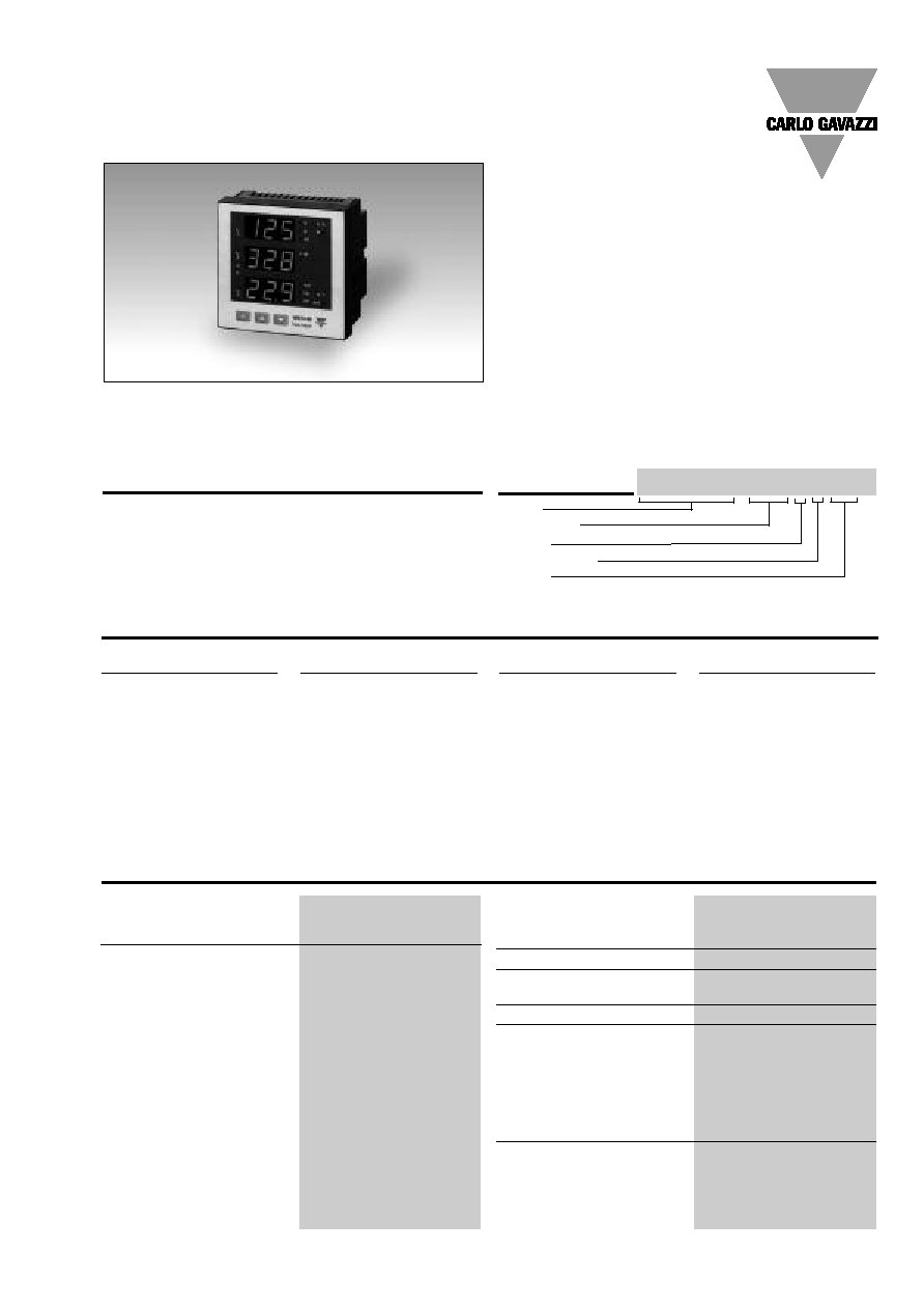
Product Description
3-phase power analyzer with
built-in programming key-
pad. Particularly recom-
mended for displaying the
main electrical variables.
Housing for panel mounting,
(front) protection degree IP65
and Profibus DP communica-
tion port.
Energy Management
Power Analyzer
Type WM14-96 "Profibus DP"
Model
Range code
System
Power supply
Option
How to order
WM14-96 AV5 3 H DG
X
Type Selection
Power supply
H:
90 to 260VAC/DC
Range codes
AV5:
380/660V
L-L
/5(6)AAC
VL-N: 185 V to 460 V
VL-L: 320 V to 800 V
AV6:
120/208V
L-L
/5(6)AAC
VL-N: 45 V to 145 V
VL-L: 78 V to 250 V
Phase current: 0.03A to 6A
Neutral current: 0.09 to 6A
Options
DG:
Profibus DP + galvanic
insulated measurig
inputs
System
3 :
1-2-3-phase,
balanced/unbalanced
load,with or without
neutral
Rated inputs
Current
3
Voltage
4
Accuracy (display, RS485)
with CT=1 and VT=1 AV5:
(@25∞C ±5∞C, R.H.
60%) 1150W-VA-var,
FS:230VLN,
400VLL; AV6: 285W-VA-var,
FS:57VLN, 100VLL
Current
0.25 to 6A: ±(0.5% FS +1DGT)
0.03A to 0.25A: ±(0.5%FS+7DGT)
Neutral current
0.25 to 6A: ±(1.5% FS +1DGT)
0.09A to 0.25A: ±(0.5%FS+7DGT)
Phase-phase voltage
±(1.5% FS +1 DGT)
Phase-neutral voltage
±(0.5% FS + 1 DGT)
Active and Apparent power,
0.25 to 6A: ±(1% FS +1DGT);
0.03A to 0.25A: ±(1% FS
+5DGT)
Reactive power
0.25 to 6A: ±(2% FS +1DGT);
0.03A to 0.25A: ±(2% FS +5DGT)
Active energy
Class 1 (start up "I": 30mA)
Reactive energy
Class 2 (start up "I": 30mA)
Frequency
±0.1Hz (48 to 62Hz)
Additional errors
Humidity
0.3% FS, 60% to 90% RH
Temperature drift
200ppm/∞C
Sampling rate
1400 samples/s @ 50Hz
1700 samples/s @ 60Hz
Display refresh time
700ms
Display
Type
LED, 14mm
Read-out for instant. var.
3x3 DGT
Read-out for energies
3+3+3 DGT (Max indication:
999 999 99.9)
Read-out for hour counter
1+3+3 DGT (Max. indication:
9 999 9.99)
Measurements
Current, voltage, power,
power factor, frequency,
energy, TRMS measurement
of distorted waves.
Coupling type
Direct
Input specifications
∑
Protection degree (front): IP65
∑
Front dimensions: 96x96mm
2
Specifications are subject to change without notice WM14-96PDS190706
WM14-96
Crest factor
< 3, max 10A peak
Input impedance
380/660V
L-L
(
AV5)
1 M
±1%
120/208V
L-L
(
AV6)
1 M
±1%
Current
0.02
Frequency
48 to 62 Hz
Overload protection
Continuos voltage/current
1.2 F.S.
For 500ms: voltge/current
2 Un/36A
Input specifications (cont.)
Data
Dynamic (reading only)
System, phase variables and
energies
Baud-rate
Up to 6Mbit/s (mainly
depending on the length of
the wiring and on the
number of instrument
belonging to the network)
Profibus
Type
DP-V0
enable only for data reading
Connections
max distance (1200m @
9.6kbit/s, 100m @ 6Mbit/s)
according to IEC61158,
9-pole connector and 10
screw terminals block.
Addresses
1 to 125, key-pad selectable
Protocol
Profibus DP-V0
Profibus DP Serial Port Specifications
Page 5: An, An Alarm
Page 6: W L1, W L2, W L3
Page 7: PF L1, PF L2, PF L3
Page 8: var L1, var L2, var L3
Page 9: VA L1, VA L2, VA L3
Page 10: VA
, W
, var
Page 11: VA dmd, W dmd, Hz
Page 12: W dmd max (*)
Page 13: Wh (*)
Page 14: varh (*)
Page 15: VL-L
, PF
,
VLN Alarm
Page 16: A max (*)
Page 17: A dmd max (*)
Page 18: hour counter (*)
(*) = These variables are
stored in EEPROM when the
instrument is switched off
Alarms
Programmable, for the VLN
and
An (neutral current).
Note: the alarm is only visual,
by means of LED on the front
of the instrument.
Reset
Independent for:
alarm (VLN
, An)
max: A dmd, W dmd
all energies (Wh, varh) and
hour counter
Password
Numeric code of max. 3
digits; 2 protection levels
of the programming data
1st level
Password "0", no
protection
2nd level
Password from 1 to 999,
all data are protected
System selection
3-phase with/without n, unbal.
3-phase balanced
3-phase ARON, unbalanced
2-phase
Single phase
Transformer ratio
CT
1 to 999
VT
1.0 to 99.9
Filter
Operating range
0 to 100% of the input
display scale
Filtering coefficient
1 to 16
Filter action
Measurements, alarms,
serial out. (fundamental var: V,
A, W and their derived ones).
Displaying
Up to 3 variables per page
3-phase system with neutral
Page 1: V L1, V L2, V L3
Page 2: V L12, V L23, V L31
Page 3: A L1, A L2, A L3
Page 4: A L1 dmd, A L2 dmd,
A L3 dmd
Software functions
Auxiliary power supply
90 to 260 VAC/DC
Power consumption
AC: 4.5 VA
DC: 4W
Power Supply Specifications

Specifications are subject to change without notice WM14-96PDS190706
3
WM14-96
EMC (cont.)
Immunity
EN61000-6-2 (class A)
industrial environment.
Pulse voltage (1.2/50µs)
EN61000-4-5
Safety standards
IEC60664, EN60664
Approvals
CE
Connections 5(6) A
Screw-type
Max cable cross sect. area
2.5 mm
2
Housing
Dimensions (WxHxD)
96 x 96 x 63 mm
Material
ABS
self-extinguishing: UL 94 V-0
Mounting
Panel
Protection degree
Front: IP65 (standard)
Connections: IP20
Weight
Approx. 400 g (pack. incl.)
Operating
0 to +50∞C (32 to 122∞F)
temperature
(RH < 90% non condensing)
Storage
-10 to +60∞C (14 to 140∞F)
temperature
(RH < 90% non condensing)
Installation category
Cat. III (IEC 60664, EN60664)
Insulation (for 1 minute)
4000VAC between
mesuring inputs and
power supply.
2000VAC between
mesuring inputs and the
communication port.
2000VAC between
power supply and the
communication port.
Dielectric strength
4000 VAC (for 1 min)
EMC
Emissions
EN50084-1 (class A)
residential environment,
commerce and light industry
General Specifications
Display pages
Display variables in 3-phase systems (in a 3-phase system with neutral)
No
1
st
variable
2
nd
variable
3
rd
variable
Note
1
V L1
V L2
V L3
2
V L12
V L23
V L31
Decimal point blinking on the right
of the display
3
A L1
A L2
A L3
4
A L1 dmd
A L2 dmd
A L3 dmd
dmd = demand (integration time
selectable from 1 to 30 minutes)
5
An
AL.n
AL.n if neutral current alarm is
active
6
W L1
W L2
W L3
Decimal point blinking on the right
of the display if generated power
7
PF L1
PF L2
PF L3
8
var L1
var L2
var L3
Decimal point blinking on the right
of the display if generated power
9
VA L1
VA L2
VA L3
10
VA system
W system
var system
11
VA dmd
W dmd
Hz
dmd = demand (integration time
(system)
(system)
(system)
selectable from 1 to 30 minutes)
12
W dmd MAX
Maximum sys power demand
13
Wh (MSD)
Wh
Wh (LSD)
The total indication is given in
max 3 groups of 3 digits.
14
varh (MSD)
varh
varh (LSD)
The total indication is given in
max 3 groups of 3 digits.
15
V LL system
AL.U
PF system
AL.U= is activated only if one of
VLN is not within the set limits.
16
A MAX
max. current among the three phases
17
A dmd max
max. dmd current among the three phases
18
h
hour counter
MSD: most significant digit
LSD: least significant digit
4
Specifications are subject to change without notice WM14-96PDS190706
WM14-96
Display pages (cont.)
al
dmd
M
var
W
V
VA
Hz
L
1
L
3
A
k
PF
h
L
2
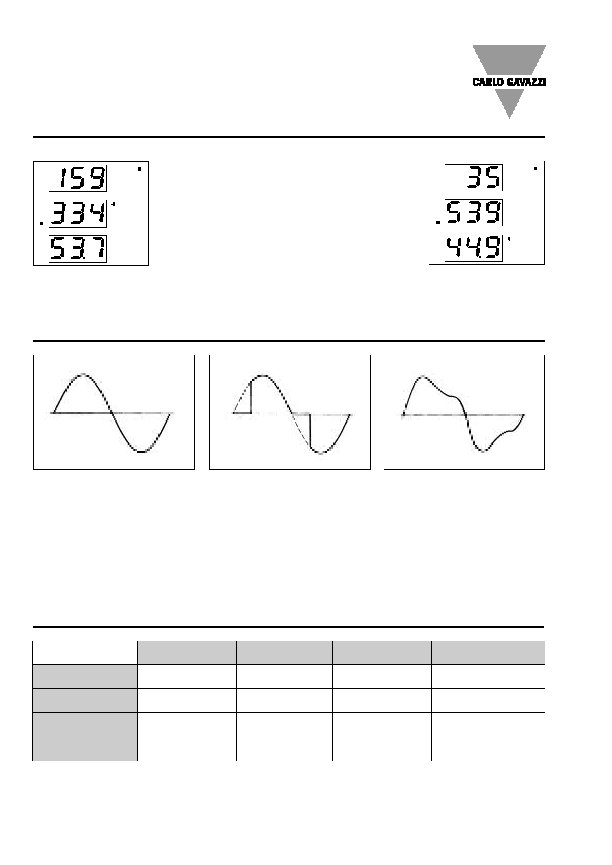
1) Example of kWh visualization:
This example is showing 15 933 453.7 kWh
al
dmd
M
var
W
V
VA
Hz
L
1
L
3
A
k
PF
h
L
2
2) Example of kvarh visualization:
This example is showing 3 553 944.9 kvarh
Figure A
Sine wave, undistorted
Fundamental content
100%
Harmonic content
0%
A
rms
=
1.1107 | A |
Figure B
Sine wave, indented
Fundamental content
10...100%
Harmonic content
0...90%
Frequency spectrum: 3rd to 16th harmonic
Additional error: <1% FS
Figure C
Sine wave, distorted
Fundamental content
70...90%
Harmonic content
10...30%
Frequency spectrum: 3rd to 16th harmonic
Additional error: <0.5% FS
Waveform of the signals that can be measured
Insulation between inputs and outputs
Measuring Inputs V
Measuring Inputs A
Profibus Port
Power Supply
Measuring Inputs V
-
-
2kV
4kV
Measuring Inputs A
-
-
2kV
4kV
Profibus Port
2kV
2kV
-
2kV
Power supply
4kV
4kV
2kV
-
NOTE: In case of fault of first insulation the current from the measuring inputs to the ground is lower than 2 mA.
Specifications are subject to change without notice WM14-96PDS190706
5
WM14-96
Energy metering
Where:
i = considered phase (L1, L2 or L3)
P = active power
Q = reactive power
t
1
, t
2
= starting and ending time points of consumption recording
n = time unit
t = time interval between two successive power consumptions
n
1
, n
2
= starting and ending discrete time points of consumption recording
Used calculation formulas
Instantaneous apparent power
Instantaneous reactive power
System variables
Equivalent 3-phase voltage
3-phase reactive power
Phase variables
Instantaneous effective voltage
Instantaneous active power
Instantaneous power factor
Instantaneous effective current
3-phase active power
3-phase apparent power
3-phase power factor
Neutral current
An = A
L1
+ A
L2
+ A
L3
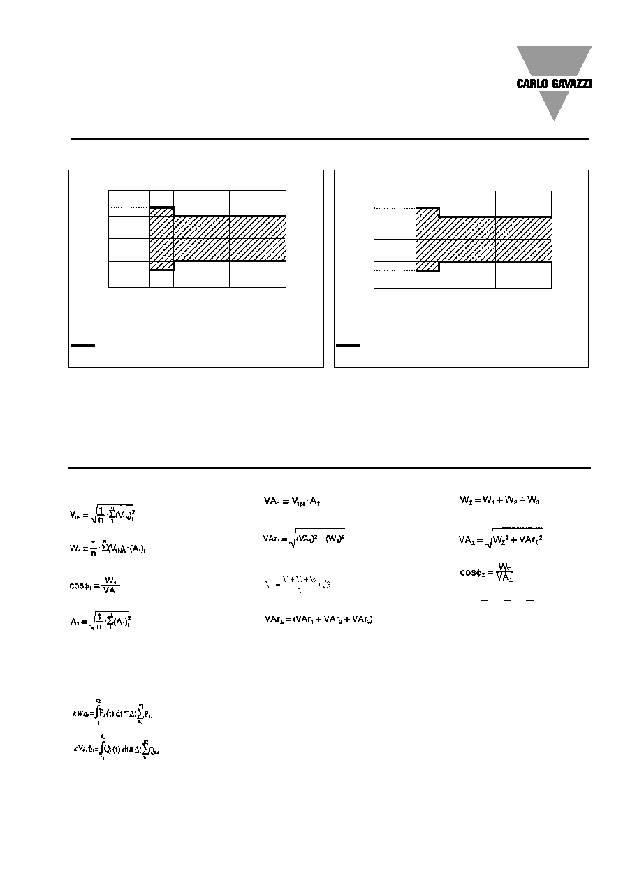
Accuracy
kWh, accuracy (RDG) depending on the current
Error
6A (Imax)
6A (Imax)
5A (In)
5A (In)
0.25A
(0.05In)
0.5A
(0.1In)
0.10A
(0.02In)
0.25A
(0.05In)
0%
Class 1 accuracy limits (Active energy)
5(6A) Start-up current: 30mA
kvarh, accuracy (RDG) depending on the current
Error
0%
Class 2 accuracy limits (Reactive energy)
5(6A) Start-up current: 30mA
PF=1
PF=L0.5
or C0.8
6A (Imax)
6A (Imax)
5A (In)
5A (In)
0.25A
(0.05In)
0.5A
(0.1In)
0.1A
(0.02In)
0.25A
(0.05In)
sin
=1
sin
=0.5
+1.5%
+1%
PF=1
PF=L0.5
or C0.8
+2.5%
+2%
+1.5%
+1%
+ 1%
- 1%
+2.5%
+2%