 | –≠–ª–µ–∫—Ç—Ä–æ–Ω–Ω—ã–π –∫–æ–º–ø–æ–Ω–µ–Ω—Ç: WM2496 | –°–∫–∞—á–∞—Ç—å:  PDF PDF  ZIP ZIP |
Specifications are subject to change without notice WM24-96DS 010806
1
∑ Class 1 (active energy)
∑ Class 2 (reactive energy)
∑ Accuracy 0.5% RDG (current/voltage)
∑ Universal utility meter and power analyzer
∑ Backlighted LCD display
∑ Front size: 96x96 mm
∑ Measurements of phase and system variables: W, W
dmd
, var,
VA, VA
dmd
, PF, V
L-N
, A, Hz
∑ Measurements of total energies: kWh, kvarh C+/C-, kvarh L+/L-
∑ Measurements of partial energies: kWh, kvarh C+/C-, kvarh L+/L-
∑ Measurements according to EN61036 and EN61268
∑ Time periods (t1, t2, t3, t4) management by means of input contacts
∑ Measurements of m
3
H
2
O and m
3
GAS by means of input contacts
∑ TRMS measurement of distorted waves (currents/voltages)
∑ Universal power supply: 18-60VAC/VDC, 90-260 VAC/VDC
∑ Instantaneous variables read-out: 4x3 1/2 digit
∑ Energies, water, gas, variables read-out: 1x7 1/2 digit
∑ Protection degree (front): IP 65
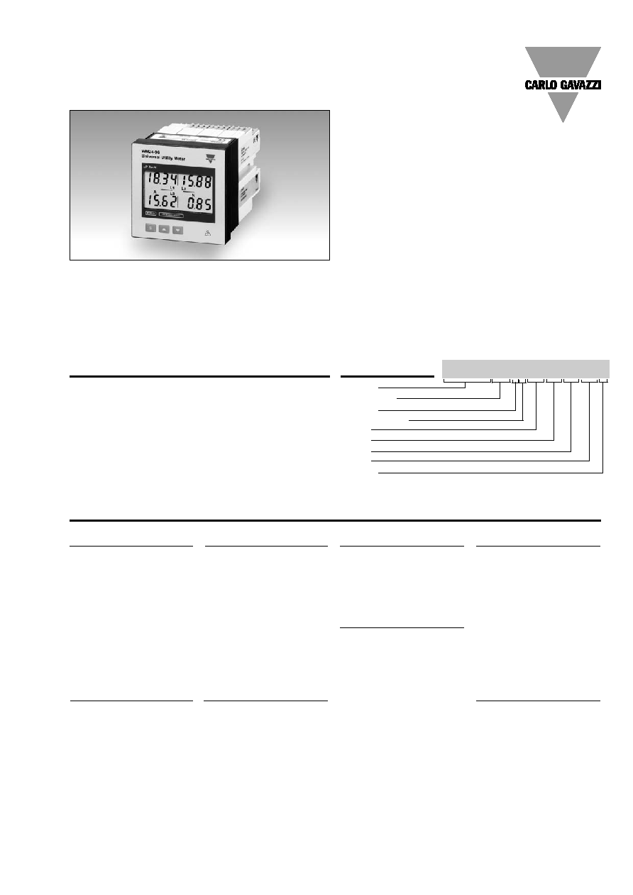
Product Description
µP-based modular universal
utility meter and power ana-
lyzer with built-in program-
ming key-pad.
Particularly recommended for
the analysis of the electtrical
variables, for the multi time
periods (t1, t2, t3, t4) energy
metering and water/gas
metering. Housing for panel
mounting and IP65 (front)
protection degree.
Energy Management
Modular Universal Utility Meter and Power Analyzer
Type WM24-96
Type selection
Power supply
A:
24 VAC -15 +10%
50-60Hz
B:
48 VAC -15 +10%
50-60Hz
C:
115VAC -15 +10%
50-60Hz
D:
230 VAC -15 +10%
50-60Hz
L:
18 to 60VAC/VDC
H:
90 to 260VAC/VDC
Range code
AV4:
208VLL/1/5(6)AAC
-20%
Un +20%
AV5:
400VLL/1/5(6)AAC
-20%
Un +15%
AV6:
100VLL/1/5(6)AAC
-20%
Un +15%
AV7:
660VLL/1/5(6)AAC
-30%
Un +15%
50-60 Hz for all input mod-
ules. Module not removable.
∑ Up to 2 pulse outputs and up to 2 alarm outputs
∑ Up to 3 digital inputs for the time period and H
2
O and
GAS meters management
∑ MODBUS/JBUS (RTU) Protocol
∑ Optional RS232, RS422/485 serial ports
Slot C (redundant output or
digital inputs)
XX:
None
R1:
Single relay output
(AC1-8AAC, 250VAC)
R2:
Dual relay output
(AC1-8AAC, 250VAC)
O1:
Single open collector
output (30V/100mADC)
O2:
Dual open collector
output (30V/100mADC)
D1:
3 digital inputs
D2:
3 digital inputs +
aux output
Options
X:
None
S:
RS232 serial port
Model
Range Code
System
Power Supply
Slot A
Slot B
Slot C
Slot D
Options
Ordering Key
WM24-96AV53H XX XX XX XX X
System
3:
Three-phase,
unbalanced load,
with or without
neutral
Slot B (communication)
XX:
None
S1:
Serial port,
RS485 multidrop,
bidirectional
Slot A
XX:
None
Slot D (alarm output)
XX:
None
R1:
Single relay output,
(AC1-8AAC, 250VAC)
R2:
Dual relay output,
(AC1-8AAC, 250VAC)
O1:
Single open collector
output (30V/100mADC)
O2:
Dual open collector
output (30V/100mADC)
NOTE: max digital output (alarms and/or pulses): 2, any exceeding output is redundant.
NOTE: with the A, B, C, D types power supply, only an open collector module or a single relay output module can be
used. The instrument can be fully equipped only with L and H type power supply.
2
Specifications are subject to change without notice WM24-96DS 010806
WM24-96
no parity, 1 stop bit
Baud-rate
9600 bauds
Protocol
MODBUS/JBUS (RTU)
other characteristics
as per RS422/485
Pulse outputs (on request)
Number of outputs
up to 2
Type
programmable from 1 to 1000
pulses
V
ON
1.2 VDC/ max. 100 mA
V
OFF
30 VDC max.
Outputs conectable to the
total and/or partial energy
meters
Pulse duration
220 ms (ON),
220 ms (OFF)
according to DIN43864
Insulation
By means of optocuplers,
4000 V
RMS
output to measu-
ring inputs,
4000 V
RMS
output to power
supply input.
Notes
The outputs can be either
open collector type or relay
type (for the relay outputs
refer to the specifications
described in the "alarm out-
puts").
RS422/RS485
(on request)
Multidrop
bidirectional (static and
dynamic variables)
Connections
2 or 4 wires, max. distance
1200m, termination directly
on the instrument
Addresses
255, selectable by key-pad
Protocol
MODBUS/JBUS (RTU)
Data (bidirectional)
Dynamic (reading only)
System and phase variables:
see table "display pages"
Static (writing only)
All the configuration parameters,
activation of the static output.
Data format
1 start bit, 8 data bit,
no parity,1 stop bit
Baud-rate
9600 bauds
Insulation
By means of optocouplers,
4000 V
RMS
output to
measuring input
4000 V
RMS
output to
supply input
RS232
(on request)
bidirectional (static and
dynamic variables)
Connections
3 wires, max. distance 15m,
Data format
1 start bit, 8 data bit
Number of measure inputs
Current
3
Voltage
4
Digital inputs
(on request)
AQ1038
Number of inputs: 3 (voltage
free)
Reading voltage
24VDC/1mA
Input frequency
Max. 20Hz, dutycycle 50%
Contact 1 purpose
key-pad programming lock
(when the contact is closed).
Contact 2-3 purpose
To be used in 3 different ways:
∑ time period selection
(t1-t2-t3-t4) and W
dmd
,
VA
dmd
synchronization;
∑ Gas total meter, and night
and day tariffs selections
∑ GAS and WATER, total
meters;
AQ1042
Number of inputs:
3+excitation output (AUX)
(16V<Aux<24VDC, max 15mA)
other characteristics like
AQ1038
Accuracy (display, RS232, RS485)
Ib:5A; Pn= Ib* Un
Current
0.003Ib to 0.2Ib: ±(0.5%
(@ 25∞C ± 5∞C, R.H.
60%)
RDG + 3DGT); 0,2Ib to
Imax: ±(0.5 RDG + 1DGT)
Phase-neutral voltage
Range Un: ±(0.5% RDG
(@ 25∞C ± 5∞C, R.H.
60%)
+ 1DGT)
Frequency
±0.1 Hz
Active power/energy
Class 1 according to
(@ 25∞C ± 5∞C, R.H.
60%)
EN61036 (I start-up: 20mA)
Reactive power/energy
Class 2 according to
(@ 25∞C ± 5∞C, R.H.
60%)
EN61268 (I start-up: 20mA)
Apparent power
(@ 25∞C ± 5∞C, R.H.
60%)
±(1% Pn +2DGT)
Ib:1A; Pn= Ib* Un
Current
0.02Ib to Ib:
(@ 25∞C ± 5∞C, R.H.
60%)
±(0.5%RDG + 3DGT);
Phase-neutral voltage
Range Un:
(@ 25∞C ± 5∞C, R.H.
60%)
±(0.5% RDG +1DGT)
Frequency
±0.1 Hz
Active power
0.5Ib to Ib: ±(1%RDG +1DGT)
(@ 25∞C ± 5∞C, R.H.
60%)
0.02Ib to 0.5Ib:
±(1.5%RDG +3DGT)
Reactive power
0.5Ib to Ib: ±(2%RDG +1DGT)
(@ 25∞C ± 5∞C, R.H.
60%)
0.02Ib to 0.5Ib:
±(3%RDG +3DGT)
Temperature drift
200ppm/∞C
Display
Back-lighted LCD 4x3
1
/
2
digits
(instantaneous variables) or
1x7
1
/
2
digits (energy, gas,
water) 70 x 38mm
Display refresh time
700ms
Measurements
Current, voltage, power,
power factor, frequency,
energy. TRMS measurement
of a distorted wave.
Coupling type
Direct
Input impedance
208VLL 5(6)AAC (AV4):
>200 k
400VLL 5(6)AAC (AV5):
>900 k
100VLL 5(6)AAC (AV6):
>200 k
660VLL 5(6)AAC (AV7):
>900 k
Output Specifications
Input Specifications
Specifications are subject to change without notice WM24-96DS 010806
3
WM24-96
Alarm outputs
(on request)
Number of outputs
up to 2, independent
Alarm type
Up alarm, down alarm
Variables to be controlled
see the "List of the
variables that can be
connected..."
Set-point adjustment
from 0 to 100% of the
electrical scale
Hysteresis
from 0 to 100% of the
electrical scale
On-time delay
0 to 255s
Relay status
Selectable; normally
de-energized and normally
energized
Output type
Relay, SPDT type
AC 1-8A @ 250VAC
DC 12-5A @ 24VDC
AC 15-2.5A @ 250VAC
DC 13-2.5A @ 24VDC
Min. response time
150ms, filters escluded,
Set-point on-time delay: "0 s"
Insulation
By means of optocouplers,
4000 V
RMS
output to
measuring input,
4000 V
RMS
output to
supply input.
Note
The outputs can be either
relay type or open collector
type (for the open collector
output refer to the specifica-
tions described in the "pulse
outputs")
Output Specifications (cont.)
Page Variables
Up to 4 by page
Three-phase system with neutral
Page 1: V L1, V L2, V L3,
V LN
Page 2: AL1, AL2, AL3
Page 3: W L1, W L2, W L3
Page 4: VA L1, VA L2
VA L3
Page 5: var L1, var L2,
var L3
Page 6: PF L1, PF 2,
PF L3, PF
Page 7: W
, var ,
PF
, Hz
Page 8: W
, VA ,
PF
, Hz
Page 9: W dmd, VA dmd
Energy, gas, water, meter pages
See "Energy, gas, water meter
settings" table
Password
Numeric code of max
4 digits; 2 protection levels
of the programming data
1st level
Password "0", no protection
2nd level
Password from 1 to 1000, all
data are protected.
Transformer ratio
CT from 1 to 5000
VT from 1.0 to 1999, where
CT x VT
10000
Power demand (dmd)
Integration time
Programmable from 1 to 30 min
Filter
Filter operating range
From 0 to 100% of the
input electrical scale
Filtering coefficient
1 to 16
Filter action
Measurements, alarms, serial
port (fundamental variables:
V, A, W and their derived ones).
Software Functions
AC voltage
90 to 260 VDC/VAC
18 to 60VDC/VAC
24 VAC -15+10% 50-60Hz
48 VAC -15+10% 50-60Hz
115VAC -15+10% 50-60Hz
230 VAC -15+10% 50-60Hz
Power consumption
30VA/12W (90 to 260V)
20VA/12W (18 to 60V)
Supply Specifications

4
Specifications are subject to change without notice WM24-96DS 010806
WM24-96
residential, commercial and
light industry environment
Immunity
EN 61000-6-2 (class A)
industrial environment
Other standards
Safety
IEC 61010-1, EN 61010-1
Product
IEC 60688-1, EN 60688-1
Approvals
CE, UL, CSA
Connections 5(6)A
Screw-type, max 2.5 mm
2
wires
(2 x 1.5mm
2
)
Housing
Dimensions
96x96x140 mm
Material
ABS, NORYL, PC (front)
self-extinguishing: UL 94 V-0
Protection degree
Front: IP65, NEMA4X, NEMA12
Connections: IP20
Weight
Approx. 400 g (packing incl.)
Operating temperature
0 to +50∞C (32 to 122∞F)
(R.H. < 90% non-condensing)
Storage temperature
-10 to +60∞C (14 to 140∞F)
(R.H. < 90% non-condensing)
Installation category
Cat. III (IEC 60664)
Pollution degree
2
Key-pad lock
by means of a rotary switch
placed behind the display or
by means of a contact (in
case of presence of the
digital inputs modules)
Insulation
4000 V
RMS
between all
inputs/outputs to ground
Dielectric strength
4000 V
RMS
for 1 minute
EMC
Emissions
EN 61000-6-3 (class A)
General Specifications
Waveform of the signals that can be measured
Figure A
Sinewave, undistorted
Fundamental content
100%
Harmonic content
0%
A
rms
=
1.1107 | A |
Figure B
Sinewave, indented
Fundamental content
10...100%
Harmonic content
0...90%
Frequency spectrum: 3rd to 16th harmonic
Figure C
Sinewave, distorted
Fundamental content
70...90%
Harmonic content
10...30%
Frequency spectrum: 3rd to 16th harmonic
Mode of operation
Accuracy
Accuracy (RDG) depending on the current
Error
6A (Imax)
6A (Imax)
5A (Ib)
5A (Ib)
0.5A
(0.1Ib)
1A
(0.2Ib)
0.25A
(0.05Ib)
0.5A
(0.1Ib)
+1%
+4%
-4%
0%
+1.5%
-1%
EN 61036/ IEC 61036 limits (Active energy)
5(6A) Start-up current: 20mA
-1.5%
Accuracy (RDG) depending on the current
Error
+2%
+4%
-4%
0%
+2.5%
-2%
EN 61268/ IEC 61268 limits (Reactive energy)
5(6A) Start-up current: 20mA
-2.5%
PF=1
PF=L0.5
or C0.8
6A (Imax)
6A (Imax)
5A (Ib)
5A (Ib)
0.25A
(0.05Ib)
0.5A
(0.1Ib)
0.1A
(0.02Ib)
0.25A
(0.05Ib)
sin
=1
sin
=0.5
Specifications are subject to change without notice WM24-96DS 010806
5
WM24-96
Variables that can be displayed in case of a three-phase system, 4-wire connection.
No
1st variable
2st variable
3st variable
4th variable Notes
1
V L1-N
V L2-N
V L3-N
V
= system
2
A L1
A L2
A L3
3
W L1
W L2
W L3
4
VA L1
VA L2
VA L3
5
var L1
var L2
var L3
6
PF L1
PF L2
PF L3
PF
= system
7
W
PF
PF
Hz
= system
8
W
PF
VA
Hz
= system
9
W dmd
VA dmd
r.t.
r.t.= symbol of communication
Rx/Tx on the serial port
10
Wh+ (total)
It depends on the instrument
11
Wh- (total)
configuration (see also "Energy,
12
Wh (total)
gas, water settings")
13
varh (total)
14
varh L+ (total)
15
varh L- (total)
16
varh C+ (total)
17
varh C- (total)
18
m3 GAS (day)
19
m3 GAS (night)
20
m3 GAS (total)
21
m3 ACQUA (total)
22
Wh (tariff 1)
23
Wh (tariff 2)
24
Wh (tariff 3)
25
Wh (tariff 4)
26
varh (tariff 1)
27
varh (tariff 2)
28
varh (tariff 3)
29
varh (tariff 4)
Display pages
Energy, gas, water meter settings
Set 1 (total)
Wh+ (total)
Wh- (total)
varh C+ (total)
varh C- (total)
varh L+ (total)
varh L- (total)
Set 2 (total and tariffs)
Wh (total)
varh (total)
Wh t1 (partial)
varh t1 (partial)
Wh t2 (partial)
varh t2 (partial)
Wh t3 (partial)
varh t3 (partial)
Wh t4 (partial)
varh t4 (partial)
Set 3 (total and gas)
Wh+ (total)
Wh- (total)
varh C+ (total)
varh C- (total)
varh L+ (total)
varh L- (total)
m
3
GAS (day tariff)
m
3
GAS (night tariff)
Set 4 (total, gas and water)
Wh+ (total)
Wh- (total)
varh C+ (total)
varh C- (total)
varh L+ (total)
varh L- (total)
m
3
GAS (total)
m
3
WATER (total)
The instrument can be configured with four different ways of management of the meters as explained in the table below.

6
Specifications are subject to change without notice WM24-96DS 010806
WM24-96
Used Calculation Formulas
Base unit
Slot A Slot B Slot C Slot D
RS485 port
Single relay output
Single open coll. output
Dual relay output
Dual open coll. output
3 digital inputs
3 digital inputs + AUX
The available modules
The possible module combinations
∑ Alarm outputs
N∞
Variable
3-phase +
3-phase
Note
neutral no neutral
1
V
L-N
x
= system
2
W
x
x
= system
3
var
x
x
= system
4
VA
x
x
= system
5
PF
x
x
= system
6
VA
dmd
x
x
7
W
dmd
x
x
8
ASY
x
x
asymmetry
List of the variables that can be con-
nected to:
Type
N. of
Ordering
channels
code
WM24-96 400V L-L 5A (base)
AJ2400
WM24-96 208V L-L 5A (base)
AJ2401
WM24-96 100V L-L 5A (base)
AJ2402
WM24-96 660V L-L 5A (base)
AJ2403
24VAC power supply
AP1025
48VAC power supply
AP1024
115VAC power supply
AP1023
230VAC power supply
AP1022
18-60VAC/DC power supply
AP1021
90-260VAC/DC power supply
AP1020
Relay output
1
AO1058
Relay output
2
AO1035
Open collector output
1
AO1059
Open collector output
2
AO1036
Digital inputs
3
AQ1038
Digital inputs + AUX
3
AQ1042
RS485 serial port (1)
1
AR1034
RS232 serial port (1)
1
AR1039
Base unit
Slot E
RS232 port
(1)
The RS232 communication port works as
alternative of the RS485 module.
Phase Variables
Instantaneous effective voltage
Instantaneous active power
Istantaneous power factor
Istantaneous effective current
Instantaneous apparent power
Instantaneous reactive power
System variables
Equivalent system voltage
System reactive power
System active power
System apparent power
System power factor
(TPF)
Energy metering
Where:
i = considered phase (L1, L2 or L3)
P = active power
Q = reactive power
t
1
, t
2
= starting and ending time points
of consumption recording
n = time unit
t = time interval between two succes-
sive power consumption
n
1
, n
2
= starting and ending discrete
time points of consumption recording
Specifications are subject to change without notice WM24-96DS 010806
7
WM24-96
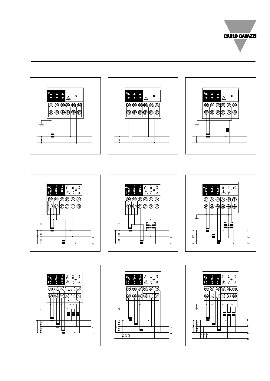
Wiring Diagrams
Single phase
L
1
N
L1
L1
N
N
L3
L3
L2
L2
U
1
1
3
3
5
5
2
2
4
4
6
6
I
I
L1
L1
L2
L2
L3
L3
8
8
7
7
10
10
9
9
L
1
N
L1
L1
N
N
L3
L3
L2
L2
U
1
1
3
3
5
5
2
2
4
4
6
6
I
I
L1
L1
L2
L2
L3
L3
8
8
7
7
10
10
9
9
L
1
N
L1
L1
N
N
L3
L3
L2
L2
U
1
1
3
3
5
5
2
2
4
4
6
6
I
I
L1
L1
L2
L2
L3
L3
8
8
7
7
10
10
9
9
CT connection
Direct connection
CT and VT connection
Fig. 1
Fig. 2
Fig. 3
Three-phase - Unbalanced load
CT connection (3-wire system) ARON
CT and VT connection (3-wire system) ARON
CT connection (4-wire system)
CT and VT connection (4-wire system)
Fig. 4
Fig. 5
Fig. 7
Fig. 8
Fig. 9
CT and VT connection (3-wire system)
Fig. 6
CT and VT connection (3-wire system)

8
Specifications are subject to change without notice WM24-96DS 010806
WM24-96
Wiring diagrams: digital input modules
Connection by
means of NPN
transistors.
Digital input
module:
AQ1042.
Connection by
means of con-
tacts.
Digital input
module:
AQ1042.
Connection by
means of con-
tacts.
Digital input
module:
AQ1038.
Connection by
means of PNP
transistors.
Digital input
module:
AQ1042.
Wiring diagrams (optional modules)
Open collector output connection.
This wiring diagram is valid also for the
open collector module with one output.
The load resistances (RC) must be
designed so that the close contact current
is lower than 100mA; the VDC voltage
must be lower than or equal to 30VDC.
1 relay output
4-wire connection of RS485 serial port
2-wire connection of RS485 serial port
2 relay outputs
Specifications are subject to change without notice WM24-96DS 010806
9
WM24-96
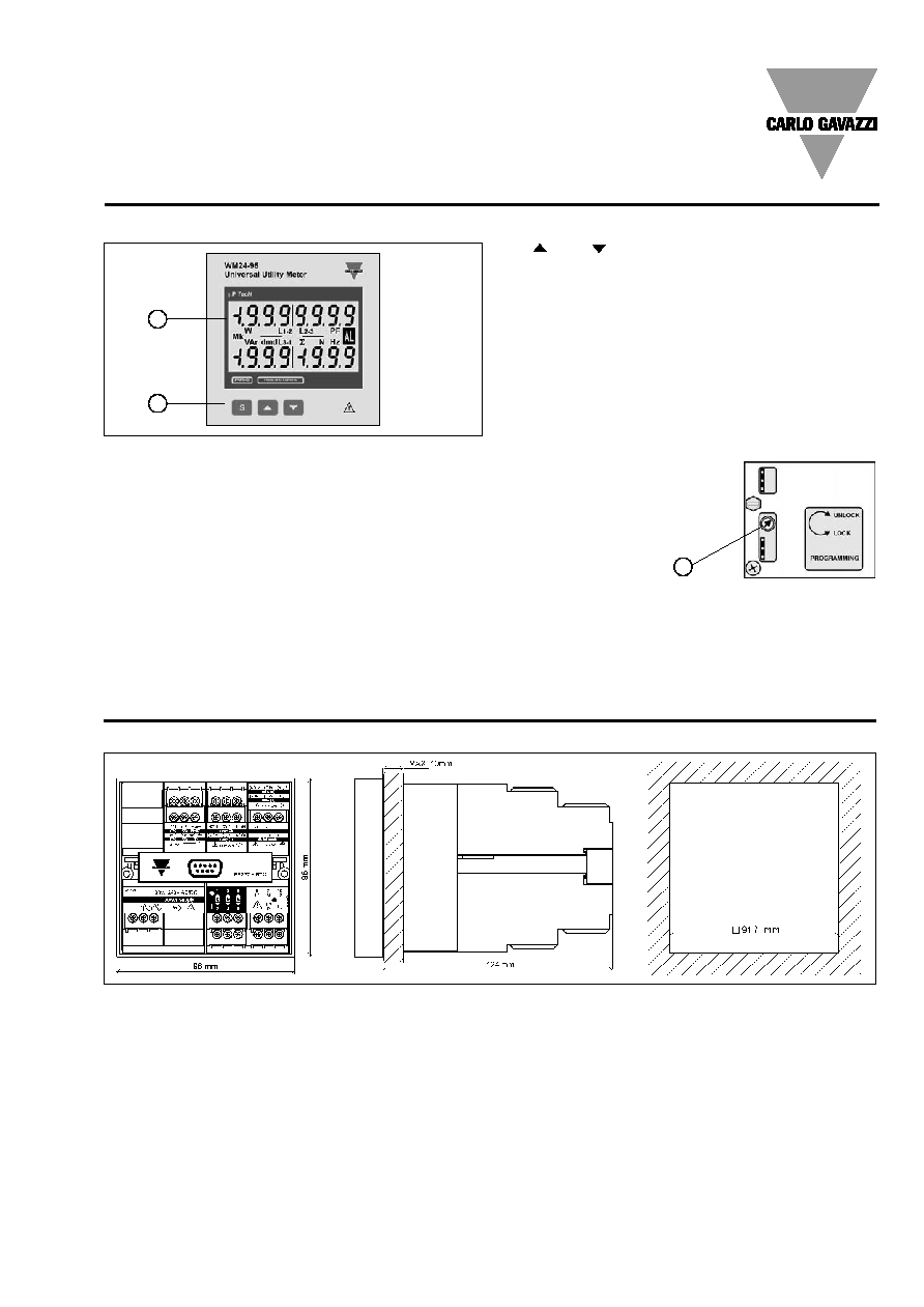
and
- for value programming
- for function selections
- for page scrolling
2. Display
Instantaneous measurements:
- 4x 3 1/2 digit (maximum read-out 1999)
Energies, gas and water:
- 1x 7 1/2 digit (maximum read-out 19.999.999).
Alphanumeric indications by means of LCD display for:
- Displaying configuration parameters
- Displaying all the measured variables.
3. Programming lock
It's possible to lock the program-
ming key-pad by means of a rotary
switch located behind the instru-
ment into the power supply slot.
Turn counterclockwise the
switch to lock the
programming key-pad.
Front Panel Description
1
1. Key-pad
The programming of configuration parameters and the
display are easily controlled by means of the 3 push
buttons:
- "S" to enter into the programming phase and to confirm
the password
2
3
Dimensions
10
Specifications are subject to change without notice WM24-96DS 010806
WM24-96
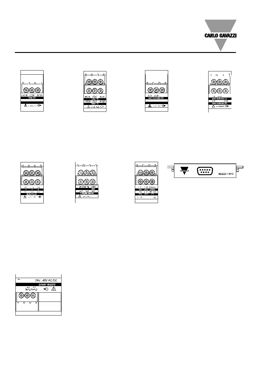
Terminal boards
AP1021
18-60 VAC/DC power supply
AP1020
90-260 VAC/DC power supply
AP1025
24VAC
power supply
AP1024
48VAC
power supply
AP1023
115VCA
power supply
AP1022
230VCA
power supply
AR1034
RS422/485 communication port
AO1035
Dual relay output
AO1059
Single open collector
output
AO1036
Dual open collector
output
AO1058
Single relay output
AQ1038
3 digital inputs
AR1039
RS232 communication port
Digital output modules
Other input/output modules
Power supply modules
AQ1042
3 digital inputs + aux