 | –≠–ª–µ–∫—Ç—Ä–æ–Ω–Ω—ã–π –∫–æ–º–ø–æ–Ω–µ–Ω—Ç: WM2DIN | –°–∫–∞—á–∞—Ç—å:  PDF PDF  ZIP ZIP |
Specifications are subject to change without notice WM2-DINDS0303
1
∑ 3-dgt/6-dgt µP-based indicator
∑ Manual or automatic scrolling of system and
single phase: kW, kVAr, PF, kWh, kVArh, I, V
avg,
VL1-N, VL2-N, VL3-N.
∑ TRMS measurement of distorted waves (voltage/current)
∑ All configuration functions selectable by
built-in key-pad
∑ Password protection of programming parameters
∑ Degree of protection (front): IP 40
∑ Standard pulse output
∑ Optional serial RS 422/485 output
∑ MODBUS, JBUS protocol.
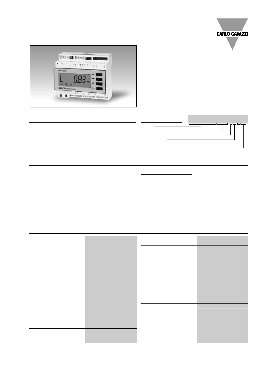
Product Description
Model
Range code
System
Power supply
1st output
2nd output
Ordering Key
WM2-DINAV53D PX
µP-based power analyzer
with a built-in configuration
key-pad. The power, PF, cur-
rent and voltage are system
and single phase measure-
ments and indications. The
housing is easy to mount on
DIN-rail and ensures a
degree of protection (front) of
IP 40.
Energy Management
Power Analyzer
Type WM2-DIN
Type Selection
System
3:
One phase,
three-phase system,
3 or 4 wires, balan-
ced load;
three phase system,
3 or 4 wires, unba-
lanced load
Range code
AV5:
250/433 VAC - 5 AAC
(max. 300 V (L-N)/
520 V (L-L) - 6 A)
Power supply
A:
24 VAC, -15% +10%,
50/60 Hz
1)
B:
48 VAC, -15%+10%,
50/60 Hz
1)
C:
115 VAC, -15%
+10%, 50/60 Hz
1)
D:
230 VAC, -15%
+10%, 50/60 Hz
(standard)
1st output
P:
Pulse, static,
DC type (standard)
2nd output
X:
No output (standard)
S:
Serial output, RS 485
multidrop bidirec-
tional
1)
Power supply
± 0.5% RDG, -15 +10% p.s.
Magnetic field
< 0.1% f.s. @ 400 A/m
Rated input
Current
2 inputs (one/three-phase
balanced load)
6 inputs (one/three-phase
unbalanced load)
Voltage
2 inputs (one/three-phase
balanced load)
4 inputs (one/three-phase
unbalanced load)
Insulation
among the voltage and the
current inputs: 2000Vrms;
among the current inputs:
2000 Vrms
Temperature drift
±250 ppm/∞C
Display
Backlighted LCD, h 13mm,
3-dgt (instantaneous meas.)
6-dgt (energies)
Input Specifications
1)
On request
Accuracy (48 to 62 Hz)
Un: 250V (AV5),
In: 5A
Voltage/current
(@ 25∞C ± 5∞C, R.H.
60%)
±1% f.s. (0 to 1.2 In,
0.5 to 1.2 Un)
Energy
(@ 25∞C ± 5∞C, R.H.
60%)
±1% RDG (kWh)
(hour time base)
±2% RDG (kvarh)
(hour time base)
(PF
0.7L/C, 0 to1.2In,
0.5 to 1.2Un)
Active power
(@ 25∞C ± 5∞C, R.H.
60%)
±1% f.s. (PF
0.7 L/C,
0 to 1.2 In, 0.5 to 1.2 Un)
Reactive power
(@ 25∞C ± 5∞C, R.H.
60%)
±1% f.s. (PF
0.8 L/C,
0 to 1 In, 0 to 1 Un)
Power factor (PF)
(@ 25∞C ± 5∞C, R.H.
60%)
±1% f.s., PF
0.7 L/C,
(0.6 to 1.2 In, 1 to 1.2 Un)
Additional errors
Humidity
< 0.3% f.s., 60% to 90% R.H.
WM2-DIN
2
Specifications are subject to change without notice WM2-DINDS0303
Pulse output
Type
From 0.1 to 999.9 pro-
grammable pulses for kWh,
KVArh, open collector (NPN
transistor)
V
ON
0.6 VDC/ max. 4 mA
V
OFF
26 VDC max.
Pulse duration
200 ms (ON),
200 ms (OFF)
Insulation
By means of optocouplers,
4000 V
rms
output to
measuring input,
4000 V
rms
output to
supply input.
Serial output (on request)
Type
RS422/RS485;
Multidrop bidirectional (static
and dynamic variables)
Connections
4 wires, max. distance
1200m, termination and/or
line bias by means of DIP-
switches directly on the
instrument
Addresses
255, selectable by key-pad
Protocol
MODBUS/JBUS
Data (bidirectional)
Dynamic (reading only)
System variables:
P, Q, PF, V
L-L
,
energies,
Single phase variables:
P
L1
, Q
L1,
PF
L1
, V
L1-N
, A
L1
,
P
L2
, Q
L2
, PF
L2
, V
L2-N
, A
L2
,
P
L3
, Q
L3
, PF
L3
, V
L3-N
, A
L3
Static (writing only)
All programming data, reset
of energy:
- partial kWh
- partial kVArh
- total kWh
- total kVArh
Stored energy (EEPROM)
999999 kWh
999999 kVArh
Data format
1-start bit, 8-data bit, no
parity/even parity, 1 stop bit
Baud-rate
1200, 2400, 4800 and 9600
selectable bauds
Insulation
By means of optocouplers,
4000 Vrms output to
measuring inputs
4000 Vrms output to
supply input
Output Specifications
Decimal point position
Instantaneous measurements:
Automatic selection accord-
ing to the current trans-
former ratio of the CT being
connected (max. indication -
single phase):
CT ratio
5 : 11.11 (25.00A)
CT ratio
50.0: 111.1 (250.0A)
CT ratio
500.0 : 1111 (2500A)
CT ratio
999.9 : 11110 (6000A)
Energy measurements:
max. resolution:1 Wh/1 VArh
min. resolution: 1 kWh/1 kVArh
Max. and min. indication
Voltage
Max. 600
min. 0
Current (CT ratio = 1)
Max. 6.00
min. 0.00
PF
Max. 1.00
min. 0.00
Power (CT ratio = 1)
Max. 5.40
min. 0.00
Active energy
Max. 999999 min. ≠199999
Reactive energy
Max. 999999 min. 0
Sampling rate
3 times / second
Measurements
System variables
kW, kVAr, PF, V
L-L
, A,
Total energies
kWh, kvarh
Partial energies
kWh, kvarh
(the meters are reset
automatically when the
values reach 14999*CT ratio)
Single phase variables
kW, kVAr, PF, V
L-N
, A
Measurement method
TRMS measurement of a dis-
torted voltage/current wave
Coupling type: Direct
Crest factor:
3
Ranges (impedances)
250 V/433 V (
1 M
)
5 AAC (
0.3 VA /
0.1
)
Frequency range
48 to 62 Hz
Over-load protection
Un: 250 (AV5), In: 5A
Continuous: voltage/current
1.2 Un/In
For 1 s
Voltage:
2 Un
Current:
20 In
Keyboard
4 keys:
"
":
- to enter programming
phase and password con-
firmation;
- for value programming
and basic measurement
scrolling.
"L":
- for confirmation of new
programmed values and
going ahead to the next
programming step,
- single phase measure-
ment scrolling.
"R":
- for the reset of the partial
counted active and/or
reactive energy.
Input Specifications (cont.)
WM2-DIN
Specifications are subject to change without notice WM2-DINDS0303
3
Password
Numeric code of max. 3 di-
gits; 2 protection levels of
the programming data
1st level
Password "0", no protection
2nd level
Password from 1 to 255, all
data are protected
Measurement scrolling
System:
Active power (kW),
reactive power (kVAr),
power factor (cos
),
current (A),
average phase-phase volt-
age (V)
total and partial active ener-
gy (kWh),
total and partial reactive
energy (kVArh)
Partial energy meters:
the counters of kWh and
kVArh are automatically
reset when the energy
reaches the value
(14999*CT).
Example: the CT is a
100A/5A so the ratio is 20,
consequently the maximum
counted energy is 299980
kWh or kVArh.
Single phase:
Active power (kW),
reactive power (kVAr),
power factor (cos
),
current (A),
phase-neutral voltage (V)
Transformer ratio
For CT up to 5000 A
Programmable ratio
0.1 to 999.9
Digital Filter
Filter operating range
0 to 100% of the
input electrical scale
Filtering coefficient
1 to 64
Filter action
On the display and on the
variable being transmitted
by the serial communication
port.
Software Functions
AC voltage
230 VAC (standard),
-15%+10% 50/60 Hz
24 VAC, 48 VAC, 115 VAC
(on request),
-15%+10% 50/60 Hz
Power consumption
7 VA
Supply Specifications
Operating temperature
0∞ to +50∞C (32∞ to 122∞F)
(R.H. < 90% non-condensing)
Storage temperature
-10∞ to +60∞C (14∞ to 140∞F)
(R.H. < 90% non-condensing)
Insulation reference voltage
300 Vrms to ground
Insulation
4000 Vrms between all inputs/
outputs to ground
Dielectric strength
4000 Vrms for 1 minute
Noise rejection
CMRR
100 dB, 48 to 62 Hz
EMC
EN 50081-2, EN 50082-2
Safety standards
IEC 61010-1, EN 61010-1
Connector
Screw-type,
max. 2.5 mm
2
wires
Housing
Dimensions
6 DIN modules,
58.5 x 89 x 107 mm
Material
ABS,
self-extinguishing: UL 94 V-0
Degree of protection
Front: IP40
Weight
Approx. 500 g
(packing included)
Approval
CE
General Specifications
WM2-DIN
4
Specifications are subject to change without notice WM2-DINDS0303
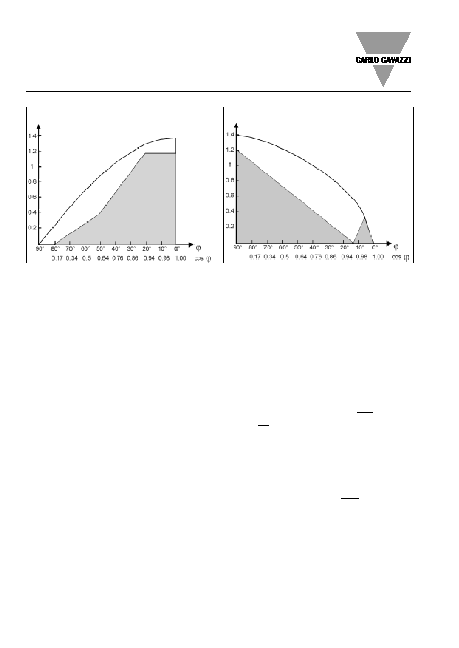
Mode of Operation
Accuracy class of the instrument as a relation of P
I/
P
n
and PF
Test conditions:
V = 0.8 to 1.2 Un,
I = 0.1 to 1.2 In,
f = 48 to 62 Hz
Input
Star
Delta
Current
voltage
voltage
AV5
Un: 230 V
Un: 398 V
In: 5 A
P
I
/Q
I
(installation power)
One phase system:
P
I
= U
I
∑ I
I
∑ cos
Q
I
= U
I
∑ I
I
∑ sin
Three phase, 3-wire system:
P
I
=
3 ∑ U
I
∑ I
I
∑ cos
Q
I
=
3 ∑ U
I
∑ I
I
∑ sin
Three phase, 4-wire system:
P
I
= 3 ∑ U
I
∑ I
I
∑ cos
Q
I
= 3 ∑ U
I
∑ I
I
∑ sin
where:
U
I
= the real star voltage of
the electrical system being
measured.
I
= the maximum phase cur-
rent of the electrical system
being measured.
cos
= the average
cos
of
the electrical system being
measured.
Pn /Qn (rated power of the
instrument):
One phase system:
P
n
= Q
n
= U
n
∑ I
n
∑ CT(ratio)
Three phase, 3-wire system:
P
n
= Q
n
=
3 ∑ U
n
∑ I
n
∑ CT(ratio)
Three phase, 4-wire system:
P
n
= Q
n
= 3 ∑ U
n
∑ I
n
∑ CT(ratio)
where:
U
n
= the rated input voltage
of WM2-DIN.
I
n
= the rated input current of
WM2-DIN.
CT (ratio)
= the value of the
current transformer ratio.
Example 1:
Model AV5.3 (3-wire system).
U
I
=
380 V (delta voltage)
I
I
= 265 A (single phase cur-
rent)
cos
= 0.85 (system power
factor) (CT=300A)
U
n
= 398 V
I
n
= 5 A
CT (ratio) =
300
= 60
5
P
I
=
3 ∑ U
I
∑ I
I
∑ cos
=
3 ∑ 380 ∑ 265 ∑ 0.85
= 148.07 kW
P
n
=
3 ∑ U
n
∑ I
n
∑ CT (ratio)
=
3 ∑ 398 ∑ 5 ∑ 60
= 206.56 kW
P
I
=
148.07
= 0.716
P
n
206.56
Example 2:
Model AV5.3 (4-wire system).
U
I
=
220 V
I
I
= 110 A (CT=300A)
Cos
= 0.85 (sin
= 0.52)
U
n
= 230 V
I
n
= 5 A
CT (ratio) =
300 A
= 60
5 A
Q
I
= 3 ∑ U
I
∑ I
I
∑ sin
= 3 ∑ 220 ∑ 110 ∑ 0.52
= 37.75 Kvar
Q
I
= 3 ∑ U
n
∑ I
n
∑ CT (ratio)
= 3 ∑ 230 ∑ 5 ∑ 60
= 207 Kvar
P
I
=
37.75
= 0.183
P
n
207
In both examples the accura-
cy of the measurement is
1% f.s. when considering the
changing of the measured
voltage from 0.9 Un to 1 Un
and the measured current
from 0.1 In to 0.9 In with a
cos
of 0.85 (sin
0.52).
P
I
/ P
n
1%
2%
1%
2%
5%
Q
I
/ Q
n
Active Power
Reactive Power
Test conditions:
V = 0.8 to 1.2 Un,
I = 0.1 to 1.2 In,
f = 48 to 62 Hz
WM2-DIN
Specifications are subject to change without notice WM2-DINDS0303
5
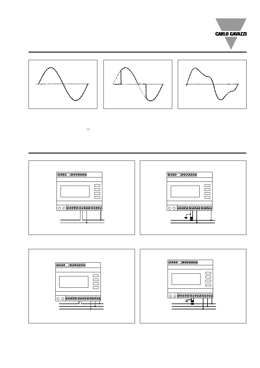
Wiring Diagrams
Single phase input connections
1
3
5 6
8 9 10 11
12 13
15 16
17 18
20
22
24
26
1
3
5 6
8 9 10 11
12 13
15 16
17 18
20
22
24
26
CT connection
Direct connection
Three phase/3-wire input connections - Balanced loads
1
3
5 6
8 9 10 11
12 13
15 16
17 18
20
22
24
26
1
3
5 6
8 9 10 11
12 13
15 16
17 18
20
22
24
26
CT connection (3-wire system)
Direct connection (3-wire system)
Fig. 1
Fig. 2
Fig. 3
Fig. 4
Waveform of the signals that can be measured
Figure G
Sine wave, undistorted
Fundamental content
100%
Harmonic content
0%
A
rms
=
1.1107 | A |
Figure H
Sine wave, indented
Fundamental content
10...100%
Harmonic content
0...90%
Frequency spectrum 3rd to 16th harmonic
Required result: additional error < 1%
Figure I
Sine wave, distorted
Fundamental content
70...90%
Harmonic content
10...30%
Frequency spectrum 3rd to 15th harmonic
Required result: additional error < 0.5%
Mode of Operation (cont.)
L
N
L
N
L1
L2
L3
L1
L2
L3
Load
Source
Load
Source
Load
Source
Load
Source
WM2-DIN
6
Specifications are subject to change without notice WM2-DINDS0303
1
3
5 6
8 9 10 11
12 13
15 16
17 18
20
22
24
26
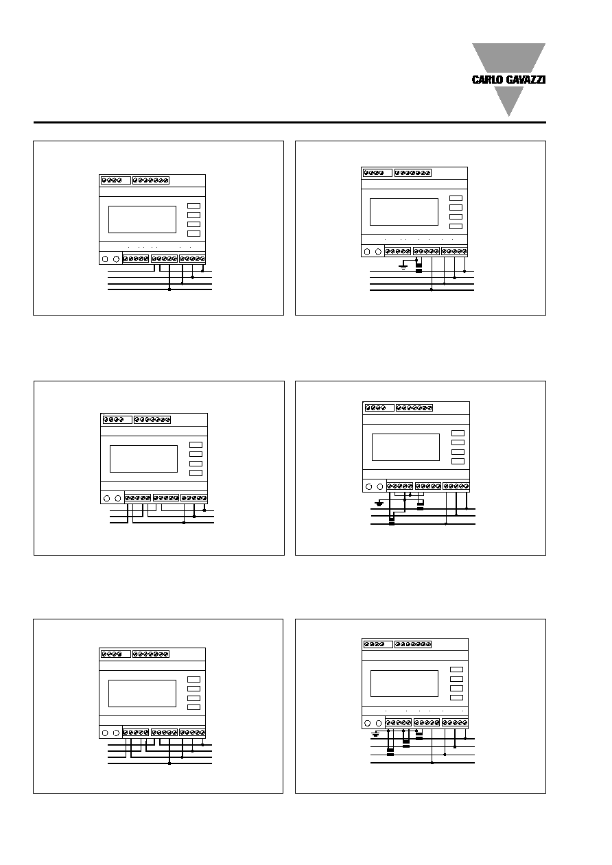
Wiring Diagrams (cont.)
1
3
5 6
8 9 10 11
12 13
15 16
17 18
20
22
24
26
CT connection (4-wire system)
1
3
5 6
8 9 10 11
12 13
15 16
17 18
20
22
24
26
1
3
5 6
8 9 10 11
12 13
15 16
17 18
20
22
24
26
CT connection (4-wire system)
Direct connection (4-wire system)
Fig. 6
Fig. 10
Fig. 9
Direct connection (4-wire system)
Three-phase, 3-wire input ARON connections - Unbalanced load
Fig. 5
Three phase, 4-wire input connections - Balanced loads
1
3
5 6
8 9 10 11
12 13
15 16
17 18
20
22
24
26
CT connection (3-wire system)
Three phase, 4-wire input connections - Unbalanced load
Fig. 7
L1
L2
L3
N
L1
L2
L3
N
L1
L2
L3
L1
L2
L3
N
L1
L2
L3
N
1
3
5 6
8 9 10 11
12 13
15 16
17 18
20
22
24
26
Fig. 8
Direct connection (3-wire system)
L1
L2
L3
Load
Source
Load
Source
Load
Source
Load
Source
Load
Source
Load
Source

WM2-DIN
Specifications are subject to change without notice WM2-DINDS0303
7
W M 2 -D IN
PO W ER A N A LYZER
R
L
KWh
KVArh
TOT
L1
L2
L3
cos
A
V
CARLO GAVAZZI
Front Panel Description
2
- To enter into the programming procedure and select
programming functions together with the "L" key.
"L":
To scroll all the single phase variable of each basic
measurement
"R":
To reset the partial counted energies (kWh, kVArh).
2. Display
Instantaneous measurements:
- 3-digit (maximum read-out 999)
Energies:
- 6-digit (maximum read-out 999999).
Alphanumeric indication by means of LCD display for:
- Displaying the configuration parameters
- All the measured variables.
3. Connection terminal blocks
4. Dip-switch
- For the selection of 2/4 wire connection, line biasing
and/or line termination (only in case of RS 485 option)
1. Key-pad
Set-up and programming procedures are easily controlled
by the 4 pushbuttons.
"
" and "
"
- To scroll all the basic measurements (system variables)
- To increase or decrease programming values
3
4
Sequence of the variables on the display
L
L
L
L
L
L
L
L
L
L
L
L
L
L
L
L
L
L
L
L
L
L
L
L
SINGLE PHASE VARIABLES
PHASE 1
PHASE 2
PHASE 3
V
L1 - L2 - L3
V
(V )
L1-N
(V )
V
L2
(V )
V
L3
I
L3
L2
I
L1
I
L1 L2 L3
L1 L2 L3
kW
L1 L2 L3
kVAr
L1 L2 L3
L1
L1
L1
I
L2
L2
L2
L3
L3
L3
total
partial
kVARh
kWh
kWh
kVARh
cos
cos
cos
cos
kW
kW
kW
kVAr
kVAr
kVAr
L1
L2-N
L3-N
(average
total
partial
SYSTEM
VARIABLE
1
WM2-DIN
8
Specifications are subject to change without notice WM2-DINDS0303
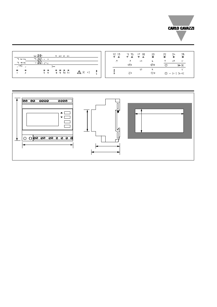
107 mm
8
9
m
m
9
0
m
m
108 mm
49.5 mm
58.5 mm
4
5
m
m
R
L
Dimensions
Upper terminal board
Lower terminal board
Terminal boards
4
6
m
m